• The move to the new server is done. There are some software and database maintenance updates in process. This has us passing the hat around to help out. We appreciate any donations. Seriously, even a dollar helps. The payment page may be found here - https://www.audiokarma.org/support.html

Improving the Fisher X-101C

Dear all

I know that everybody are anxious to see the modified drawings, Hopefully at the end of this month and starting the next one I'll upload the drawings.

Thanks for your patience!
 
Hi all,

Did the finished schematics ever get posted? I would really like to see them. I hope the schematics will include the EFB regulator itself.

Great read. Thanks.
 
Final Schematics

Just acquired an X-100-C and I am anxious to begin the mods. Did you finish the final schematic ? If so, where is it posted. Thanks
 
Final Schematic

In response to all of those who have inquired both here on the forum and by PM directly to me, I would like to publicly thank Joe Strickland (audmod01) for undertaking the integration of all the modifications contained in this thread, into the original Fisher Schematic for the X-101C. His attention to accuracy and detail are unsurpassed, and he worked selflessly to get the job done. Joe has his own X-101C project going, and is implementing these modifications into the restoration of his unit. His thread on that effort can be found here:

http://www.audiokarma.org/forums/showthread.php?t=654505

Due to the file size, I could not upload the schematic to this post (unless Joe you can alter it to fit?), although either Joe or I can supply a PDF file of the finished schematic as an attachment to an email for those who are seriously interested in applying the modifications to their own unit. Joe is new to the Fisher community here, but is already making his considerable talents known. Collaborations such as this are what make this community second to none!

Dave
 
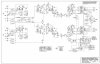
Final Schematic -- Reduced File Size

Joe converted the original pdf file into two separate jpg files (schematic and BOM), allowing them to be posted here. While they are too small to retrieve any detail information, they are still quite useful in depicting the extent of the modifications done, as compared to the original schematic of the X-101C. Again, my thanks to Joe for making the schematic, and its posting here possible!

Dave
 

Attachments

  • Fisher X101C Mods Rev A-1.jpg
    Fisher X101C Mods Rev A-1.jpg
    79 KB · Views: 195
  • Fisher X101C Mods Rev A-2.jpg
    Fisher X101C Mods Rev A-2.jpg
    53.1 KB · Views: 167
Fisher X-101C Modifications Document

Dave and I both collaborated on the document showing the modified schematic and the BOM listing the parts added or changed. These should help anyone who wants to understand the changes and make a list of parts to order. Considerable leeway is given in the BOM since, as Dave mentioned, parts often are superseded or become no longer available for various reasons. Of particular importance is to carefully choose the electrolytics to be installed on the new low voltage DC supply. There is little vertical room under the chassis, so check the stack-up of cardboard insulation pad plus perf-board then the height of the capacitors to make sure they will fit with some room to spare when the bottom cover is installed.

This community is indeed fortunate to have such a dedicated and professional person such as Dave to provide so much help to the Fisher community here. Dave worked with me and contributed many hours of checking and recommending changes to the documents as we went along. We believe the results will truly be helpful to others.

Dave and I both will be able to provide the documents by private e-mail if he is unsuccessful in up-loading the document to storage here. I originally did the document in Photoshop, but also sent Dave smaller *.jpg files that are considerably smaller in size, but still are 300dpi resolution.

All the Best to everyone!

Joe
 
Thank you Joe.
You've done us a great service.
Getting to know Dave and work with him is such a pleasure, isn't it?
 
Thanks

Don;

Yes I thoroughly enjoyed working with Dave. It helped me to dig in so deeply into the schematic while fitting in Dave's sketches of portions of the circuitry. As I worked on the schematic it all began to make sense.

Before I begin any given project, one of my first steps is to acquire service manuals, or at least a schematic to study. Often I find the internet sources have poorly scanned images of the original drawings. I usually take time to import them into Photoshop and work to improve the readability and organization of a schematic. A good example is the many Ryder's schematics available from NostalgiaAir. They are usually not clear and crisp and need considerable work before they become easily readable to my poor eyes.

Doing schematics, block diagrams, assembly diagrams & instructions, bills of material etc. were one of my tasks at Collins Radio/Alcatel before I retired. Many system level documents were the result of my work in collaboration with other good workers that I interfaced with. We had some great people to work with. That is one reason why I enjoyed working with Dave so much. It brought back many good memories. Now I have some new ones.

Joe
 
.....
Doing schematics, block diagrams, assembly diagrams & instructions, bills of material etc. were one of my tasks at Collins Radio/Alcatel before I retired.
.....

Aha! Collins Radio. I was only there as an intern 1968-1970 but it remains probably the most organized company I ever worked for, even compared to GTE, Sperry-Univac, and Motorola. Their adherence to rigid standards is second to none, both with equipment and documentation.
 
Thanks to Dave for all of his inspired work and putting up with me off-line with my litany of questions. He is a gentleman and scholar.

Is anyone up the task of putting together an instruction set for working through the changes? The schematic i s one thing, the actual mod is something else !

I have a pristine X-101-C i bought at a stereo shop that was going out of business . They had it on a display shelf and the propietor said he didn't know if it worked. I brought it up on a variac and it has about 25 hours on it. Plays like a dream - i think one if the multisection caps was replaced, along with one output coupling cap, but other than that its a virgin with about 1/2 of the tubes proudly bearing the Fisher logo.

I want to go at the mods slowly and will be happy to take pictures

Maybe several of us can work together on an "instruction manual"
 
I did have one other thought to share.

I don't want to mount the required transformer on the chasis so i was thinking about using the center channel speaker terminals to bring the 25.2 VAC on to the chasis (ground separately) and putting the transformer in a small external box. I would power the transformer through one of the two aux outlets on the back so that it would turn on when the X-101-C was powered on. This would save drilling the chasis. The circuit card could be mounted in the place Dave described in one of earler posts. Since i have no plans for a center channel, it seems like this would work. I could eliminate or terminate the center channel connections Dave desribed in the schematc.

Any thoughts???
 
Dog -- Thanks for the kind comments! If I may, it would seem that you are caught between wanting to do the modifications and not wanting to make any physical changes to the unit to implement them -- ergo, the answer to use an umbilical set up. I would suggest that from a long term and practical standpoint, that approach has a number of concerns:

1. While you may want to maintain the pristine element of your unit by not physically modifying it to accommodate the transformer, nothing screams "modification" more than a unit that now has to have an umbilical attachment to a separate chassis or device to make it operate.

2. Over time, I have found (from my own such efforts long ago) that umbilical modifications come off as clumsy and less than professional: This equipment is already heavy, so any attached umbilical devices make it more awkward to carry or maneuver about.

3. On the practical side, the center speaker terminal strip has only two connection posts, while the secondary of the transformer has three leads that connect into the circuit. Also, if the power to the external transformer ever becomes accidentally unplugged from the rear auxiliary receptacle, then all bias is lost on the output tubes (causing all of them to immediately red plate). This could also happen if the side of the AC power switch that services the rear receptacles fails, while the side powering the amplifier did not. On the other hand, if you accidentally plug the transformer into a receptacle that is powered all the time, then the preamp tubes will have their heaters lit 24/7, but without any current flowing between the cathode and plate elements. This will eventually poison the cathodes causing the tubes to rapidly wear out much faster than they normally would -- even if they were running properly 24/7.

Against this, mounting the transformer on the unit eliminates all of these concerns, at the expense of drilling four holes in the chassis. Yes, it's a permanent change to the chassis. But as a corollary to #1 above, nothing screams "professional" like a modification that is well executed, which mounting the transformer neatly on the chassis produces.

Remember too that the backdrop of all of this is the results that the modifications themselves produce -- which in this case is nothing short of outstanding. Consider that:

1. Power output is greatly increased, while distortion at the increased power level is greatly reduced from that which the stock unit produces at its lower power output capabilities at all frequencies.

2. Output tube quiescent current is greatly reduced over that of the original design, adding significantly to output tube life expectancy.

3. With less quiescent current draw through the output tubes and power supply, the unit runs notably cooler.

And, it warms up more quickly now, is easier on the small signal tube heaters, and the list goes on. And these are only the benefits from adding the small power supply and the EFB(tm) circuits. The rest of the modifications add significantly to the operating capabilities of the unit as well.

The point being that there are modifications, and then there are modifications. Many of us have seen modifications that were a "modification in search of an improvement" (meaning that the results produced are purely subjective or even questionable at best), or modifications that were so poorly thought out or executed as to actually detract from the performance of the original device. Audmod01 is desperately trying to undo that very type of effort on the unit he has now -- before he can even begin the modifications themselves.

But the modifications presented here are nothing like that. The wide spread improvements achieved from this set of modifications far more than outweigh the small penalty of the slight physical modifications required. And each portion of the modification adds its own factual enhancement to the operation of this unit in today's audio environment. That it can all be had within the same space of the original footprint is just another part of the attractiveness of the overall modification package in the first place.

Don may (or may not) have more to say on this. He has lived with his modified unit now for over a year, having good experience then with it in modified form, as well as before all the modifications were performed.

Ultimately, how you approach the modifications is your decision, with no judgement from me as to how you choose to approach them. I just wanted to give you some points to consider as you start putting your thoughts together towards that end.

I hope this helps!

Dave

 
Where to out the transformer ?

Dave

Thank you for you analysis. Learned as always

Frankly, i did not even consider a "faikure mode" analysis. I guess i am having trouble bringing myself to take my Makita to the chasis, but as you point out, that may be the best engineered approach.

- Fred
 
Dave & Joe,

If you email the hi-res schematics to ak.pdfs@gmail.com I will upload them to the AK database. There is a 20MB size limit per document. This is the best way to distribute high quality documents.
 
Doggitz,
With a wooden cabinet on the X-101-C, you'd never know a modification was done.
Actually, to any untrained eye, mounting the filament transformer does not really look like a modification even when the X-101-C is not in a cabinet.
I have only positive things to say about mounting the fil transformer on the top deck of the unit.

You might think, Ah, but I want to watch the tube glow. Great. Eventually that thought pattern will wear off though, especially when you realize that the front panel is designed to obscure the tubes from view.
Best of luck,
Don
 
Last edited:
Back
Top Bottom