

You are using an out of date browser. It may not display this or other websites correctly.
You should upgrade or use an alternative browser.
You should upgrade or use an alternative browser.
Improving the Fisher X-101C
- Thread starter dcgillespie
- Start date

tube-a-lou
Addicted Member
Me too, but that's why I picked up a KX200 and restored that just to hear a
difference.
Tube
difference.
Tube

The X-1xx series of amplifiers were always the lower priced Fisher offerings, but of course still had all the qualities that were hallmarks of Fisher: Very quiet operation, smooth operation, great sound, and classically good looks that were timeless in appeal. I can't think of any other manufacturer that hit all these areas quite the way Fisher did.
As for sonic compromises, no criticism of Fisher is being leveled here. Understand that design compromises made back in the day could be made with virtually no sonic penalties at the time, because the source material of the day simply didn't have a response range that could be limited by the compromises employed. Today however, the frequency range of source material is greater than ever, which makes yesterday's compromises become apparent today. The effort here then is hardly to cast the X-101C as a poor design, but simply to bring it up to its full potential to handle the best of today's source material, and update a few of its features along the way to make it more practical in today's audio world.
Dave
As for sonic compromises, no criticism of Fisher is being leveled here. Understand that design compromises made back in the day could be made with virtually no sonic penalties at the time, because the source material of the day simply didn't have a response range that could be limited by the compromises employed. Today however, the frequency range of source material is greater than ever, which makes yesterday's compromises become apparent today. The effort here then is hardly to cast the X-101C as a poor design, but simply to bring it up to its full potential to handle the best of today's source material, and update a few of its features along the way to make it more practical in today's audio world.
Dave
Project Summary
This project was initiated by Audiodon, from his desire to see how EFB(tm) could enhance the performance of his ratrig Fisher X-101C, because in particular, it employed the heater string bias design that Fisher ultimately employed in a great many of their amplifiers. With such wide spread use, it was felt that doing an EFB work up on his amplifier would then provide a base to build from for all the other Fisher designs using the heater string bias technique.
Along the way, a couple more requests were added to (1) convert the old Reverb In/Out jacks into Preamp Output/Power Amp Input jacks, and (2) install a tone control bypass switch if possible -- both being features I had installed into his X-1000 amplifier. This then became the basis of the project, to which I added revising the output connections so that the Common output terminals operated at ground level. Beside the practical benefits this produces, it also allows the X-101C to then maintain absolute phase, which in stock form, it does not.
When first received, all tubes were performance tested, replaced as necessary, with the output tubes matched up for best performance pairing. Additionally, some wiring miscues and defective components were corrected/replaced to place the unit in proper stock operating condition, this to allow a performance base line to be generated. That determined that a stock, properly operating X-101C can produce 20 watts RMS per channel with both channels driven, with 1 kHz distortion averaging ~ 1.4% at 20 watts output in each channel. Frequency response was down 1.8 db at 20 kHz with the volume control at max, but varied significantly with the control's setting, being -2.2 db with the volume control at a normal listening setting. The stability of the stock amplifier was very good. With that, the modification work began.
A small transformer was mounted on the top of the chassis to provide power for a new power supply board that was mounted underneath the chassis, in a cleared out area under the power transformer. This board supplies filtered DC to power (1) the small signal tube heaters originally powered by output tube current draw, (2) a portion of the new EFB circuits, and (3) an op-amp buffer stage needed to accommodate the new Preamp Output/Power Amp Input jack feature. A plus feature of the new heater supply, is that the heaters are now configured in such a way that a failure of any combination of heaters will not affect the operation of those remaining tubes that are still good. In the stock design, a failure of any one tube would render the amplifier completely silent.
Revision of the output connections then got underway, requiring removal of the powered center channel output feature, rewiring the speaker switch to allow it to work properly with the revised output connections, and swapping the primary leads of the OPTs. Along the way, the wiring for the headphone jack was also corrected, which in stock form has the stereo channels reversed. The speaker switch can no longer disable the phone jack as in the original design, but the internal load resistors are still brought into the circuit when the speakers are turned to any off position as before. With this move, absolute phase integrity is now maintained from all inputs to the speaker/phone outputs, except those signals applied to the Tape Monitor, which produces an opposite phase output relative to the other inputs. This is as it was in the stock design, as is the phase change that takes place at the Recording Output jacks from that applied to the inputs.
The signal path was then altered to take the Reverb In/Out jacks out of the signal path, and reinsert them into the signal path at the output of the preamp/control section, and input to the power amplifier section. In addition to the rerouting/rewiring this caused, this also required the installation of a small op-amp buffer stage mounted to the back of the balance control, to drop the high impedance output of the preamp/control circuits down to a low impedance level that will eliminate the effects of cable capacitance for any interconnects that are used with these jacks. The new op-amp buffer stage has an output impedance of 100 ohms, which is very low for the requirements, and also makes response of the modified amplifier completely independent of the volume control setting. Before the installation of the buffer stage, the balance control was first reinstalled so that its electrical center coincided with a 12:00 noon setting of the control. Both the new preamp/control and the power amp sections now individually maintain absolute phase integrity.
With the lowered output impedance of the preamp/control section, the transient response and stability of the power amplifier sections was significantly disturbed. This required a step network to be installed across the plate resistor of the AF amplifier stage, and a new dual tap feedback network to be installed, replacing the old network. This arrangement produced power amplifiers with the same response as before (-1 db at 50 kHz), but with greatly improve transient response and stability over that of the original design. Use of the new dual tap feedback network makes installation of the revised output connections mandatory, as this network can only function properly if the Common terminals operates at ground level.
The installation of EFB was finished out for the output stage, producing significant gains in power amplifier performance. With EFB, each channel can now produce 34.5 watts RMS with both channels operating, producing just .14% THD in his scenario, at 1 kHz at this power level. This is a 10 fold reduction in distortion, at a 172.5% increase in power output over that of a properly operating stock X-101C. Additionally, where as the original design operated the output tubes at 100% of rated dissipation when properly biased, the EFB controlled output stages operate the tubes at just 72% of rated dissipation, producing the power and distortion figures noted, as well as greatly extended tube life, and notably cooler operation.
Finally, the tone control bypass feature was installed, which required modification of the line/tone amplifier stages to extend and flatten their individual response. This also flattened the signal available at the Recording Output jacks as well. Opportunity was also taken to to flatten the on-center response of the tone control networks, for better performance from them when they are engaged. The response of the new preamp/control section is now down just .2 db @ 20 kHz, and .25 db through the entire amplifier. To help maintain stability with the improved line/tone stage response, the original PEC EQ networks mounted on the rear of the EQ switch for the low level preamps were removed, and a discrete RIAA only EQ network was mounted over in the phono preamp tube area.
The completed amplifier maintains all the Fisher qualities that endear so many to Fisher in the first place. It is still very quiet. All the controls still operate quietly and smoothly. The wonderful physical appearance is basically unchanged. But now, this amplifier is up to whatever signal source you want to throw at it, and it will take in all in stride with improved detail and clarity, and unbelievable punch, without any tendency towards being strident or sibilant. It is a change that is as striking sonically, as the change is in measured performance in the lab. And, it will do this while operating cooler, and with longer tube life to boot.
A few final pics:
1. The only appearance change is the addition of a new small power transformer, positioned so that the original chassis controls are still easily accessible.
2. After 3 hours of operation, the power transformer operates at just 125 F in my 70 F listening room.
3. The new small transformer reaches just 123 F in the same time frame and environment.
4. Under EFB control, the output tubes now operate stress free at greatly reduced dissipation levels. This time lapse pic shows the complete lack of any plate color in the tubes.
5. Under the front panel cover, all the controls still work exactly as they did, except for the EQ switch which now does nothing, as does control of the center channel or headphone circuits by the speaker switch. The High Filter Switch is now a Tone Control Engage Switch, which engages the controls in the UP position.
I'll get started on the schematics soon, and post them ASAP. Thanks to all who followed along!
Dave
This project was initiated by Audiodon, from his desire to see how EFB(tm) could enhance the performance of his ratrig Fisher X-101C, because in particular, it employed the heater string bias design that Fisher ultimately employed in a great many of their amplifiers. With such wide spread use, it was felt that doing an EFB work up on his amplifier would then provide a base to build from for all the other Fisher designs using the heater string bias technique.
Along the way, a couple more requests were added to (1) convert the old Reverb In/Out jacks into Preamp Output/Power Amp Input jacks, and (2) install a tone control bypass switch if possible -- both being features I had installed into his X-1000 amplifier. This then became the basis of the project, to which I added revising the output connections so that the Common output terminals operated at ground level. Beside the practical benefits this produces, it also allows the X-101C to then maintain absolute phase, which in stock form, it does not.
When first received, all tubes were performance tested, replaced as necessary, with the output tubes matched up for best performance pairing. Additionally, some wiring miscues and defective components were corrected/replaced to place the unit in proper stock operating condition, this to allow a performance base line to be generated. That determined that a stock, properly operating X-101C can produce 20 watts RMS per channel with both channels driven, with 1 kHz distortion averaging ~ 1.4% at 20 watts output in each channel. Frequency response was down 1.8 db at 20 kHz with the volume control at max, but varied significantly with the control's setting, being -2.2 db with the volume control at a normal listening setting. The stability of the stock amplifier was very good. With that, the modification work began.
A small transformer was mounted on the top of the chassis to provide power for a new power supply board that was mounted underneath the chassis, in a cleared out area under the power transformer. This board supplies filtered DC to power (1) the small signal tube heaters originally powered by output tube current draw, (2) a portion of the new EFB circuits, and (3) an op-amp buffer stage needed to accommodate the new Preamp Output/Power Amp Input jack feature. A plus feature of the new heater supply, is that the heaters are now configured in such a way that a failure of any combination of heaters will not affect the operation of those remaining tubes that are still good. In the stock design, a failure of any one tube would render the amplifier completely silent.
Revision of the output connections then got underway, requiring removal of the powered center channel output feature, rewiring the speaker switch to allow it to work properly with the revised output connections, and swapping the primary leads of the OPTs. Along the way, the wiring for the headphone jack was also corrected, which in stock form has the stereo channels reversed. The speaker switch can no longer disable the phone jack as in the original design, but the internal load resistors are still brought into the circuit when the speakers are turned to any off position as before. With this move, absolute phase integrity is now maintained from all inputs to the speaker/phone outputs, except those signals applied to the Tape Monitor, which produces an opposite phase output relative to the other inputs. This is as it was in the stock design, as is the phase change that takes place at the Recording Output jacks from that applied to the inputs.
The signal path was then altered to take the Reverb In/Out jacks out of the signal path, and reinsert them into the signal path at the output of the preamp/control section, and input to the power amplifier section. In addition to the rerouting/rewiring this caused, this also required the installation of a small op-amp buffer stage mounted to the back of the balance control, to drop the high impedance output of the preamp/control circuits down to a low impedance level that will eliminate the effects of cable capacitance for any interconnects that are used with these jacks. The new op-amp buffer stage has an output impedance of 100 ohms, which is very low for the requirements, and also makes response of the modified amplifier completely independent of the volume control setting. Before the installation of the buffer stage, the balance control was first reinstalled so that its electrical center coincided with a 12:00 noon setting of the control. Both the new preamp/control and the power amp sections now individually maintain absolute phase integrity.
With the lowered output impedance of the preamp/control section, the transient response and stability of the power amplifier sections was significantly disturbed. This required a step network to be installed across the plate resistor of the AF amplifier stage, and a new dual tap feedback network to be installed, replacing the old network. This arrangement produced power amplifiers with the same response as before (-1 db at 50 kHz), but with greatly improve transient response and stability over that of the original design. Use of the new dual tap feedback network makes installation of the revised output connections mandatory, as this network can only function properly if the Common terminals operates at ground level.
The installation of EFB was finished out for the output stage, producing significant gains in power amplifier performance. With EFB, each channel can now produce 34.5 watts RMS with both channels operating, producing just .14% THD in his scenario, at 1 kHz at this power level. This is a 10 fold reduction in distortion, at a 172.5% increase in power output over that of a properly operating stock X-101C. Additionally, where as the original design operated the output tubes at 100% of rated dissipation when properly biased, the EFB controlled output stages operate the tubes at just 72% of rated dissipation, producing the power and distortion figures noted, as well as greatly extended tube life, and notably cooler operation.
Finally, the tone control bypass feature was installed, which required modification of the line/tone amplifier stages to extend and flatten their individual response. This also flattened the signal available at the Recording Output jacks as well. Opportunity was also taken to to flatten the on-center response of the tone control networks, for better performance from them when they are engaged. The response of the new preamp/control section is now down just .2 db @ 20 kHz, and .25 db through the entire amplifier. To help maintain stability with the improved line/tone stage response, the original PEC EQ networks mounted on the rear of the EQ switch for the low level preamps were removed, and a discrete RIAA only EQ network was mounted over in the phono preamp tube area.
The completed amplifier maintains all the Fisher qualities that endear so many to Fisher in the first place. It is still very quiet. All the controls still operate quietly and smoothly. The wonderful physical appearance is basically unchanged. But now, this amplifier is up to whatever signal source you want to throw at it, and it will take in all in stride with improved detail and clarity, and unbelievable punch, without any tendency towards being strident or sibilant. It is a change that is as striking sonically, as the change is in measured performance in the lab. And, it will do this while operating cooler, and with longer tube life to boot.
A few final pics:
1. The only appearance change is the addition of a new small power transformer, positioned so that the original chassis controls are still easily accessible.
2. After 3 hours of operation, the power transformer operates at just 125 F in my 70 F listening room.
3. The new small transformer reaches just 123 F in the same time frame and environment.
4. Under EFB control, the output tubes now operate stress free at greatly reduced dissipation levels. This time lapse pic shows the complete lack of any plate color in the tubes.
5. Under the front panel cover, all the controls still work exactly as they did, except for the EQ switch which now does nothing, as does control of the center channel or headphone circuits by the speaker switch. The High Filter Switch is now a Tone Control Engage Switch, which engages the controls in the UP position.
I'll get started on the schematics soon, and post them ASAP. Thanks to all who followed along!
Dave
Attachments


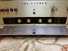
Don's ratrig is now on its way back to him, after attending to a couple of minor details. One was reflowing a noisy Fisher solder joint in the phono section, while the other was converting the old powered center channel speaker output terminals into a line level center channel output that is controlled by the X-101C's volume control. This low impedance output connection will allow Don to still connect his favorite powered sub unit up to the C now as desired, as long as it has a line level input. This output is no longer controlled by the speaker switch as it was in the original design, but it does still allow a center channel output signal to be had when needed.
So, fingers are crossed for a safe arrival back home, but anyone who has been on the receiving end of Don's shipments knows that he sets the standard in packaging such equipment for safe transportation. I simply reused the same cartons and material he shipped it down to me in, so it should arrive safely -- but fingers are still crossed.
With that, I'll get to work on the schematics, and wait for his comments now on the X-101C's makeover!
Dave
So, fingers are crossed for a safe arrival back home, but anyone who has been on the receiving end of Don's shipments knows that he sets the standard in packaging such equipment for safe transportation. I simply reused the same cartons and material he shipped it down to me in, so it should arrive safely -- but fingers are still crossed.
With that, I'll get to work on the schematics, and wait for his comments now on the X-101C's makeover!
Dave
The enlarged schematic that Don sent with the ratrig has now been marked up with all the changes made, with the different circuit sections drawn in the open border areas as individual modules to indicate the changes. A copy of this schematic has been sent back to Don now, and has also been scanned into a pdf file for me at the local Staples.
Luis -- if you will PM me with an appropriate email address, I will send the file to you so you can start your process of redrawing the original schematic to include the changes. Once finished, that schematic can be posted here to complete the modification portion of this thread.
Dave
Luis -- if you will PM me with an appropriate email address, I will send the file to you so you can start your process of redrawing the original schematic to include the changes. Once finished, that schematic can be posted here to complete the modification portion of this thread.
Dave
I sent the marked up schematic to Luis last weekend, who has graciously undertaken the task of generating a new Fisher style schematic for the X-101C from it, containing all the modifications made. As with all of us however, we work the efforts of our hobby in with the responsibilities of our daily lives. As a result, Luis only has so much time to devote to the schematic effort at this time, due to existing obligations he already has. He has promised he will get it done, but could not put any time frame on it due to his obligations.
It occurred to me then that since I emailed the marked up schematic to him, I can also email it to anyone else who is interested in the changes made, who might be waiting so as to potentially apply all or a part of the modifications to their own projects. The marked up schematic is rough, not being a traditional schematic, but rather, a series of modules drawn in the margins of the Fisher schematic to show the significant number of changes made to various areas of the unit. If you are comfortable with reading schematics, it will be easy enough to piece together.
For any who might like a pdf copy of the (very) rough draft, you can send an email request for it to me at dave@tronola.com and I'll be happy to send a copy back to you.
Dave
It occurred to me then that since I emailed the marked up schematic to him, I can also email it to anyone else who is interested in the changes made, who might be waiting so as to potentially apply all or a part of the modifications to their own projects. The marked up schematic is rough, not being a traditional schematic, but rather, a series of modules drawn in the margins of the Fisher schematic to show the significant number of changes made to various areas of the unit. If you are comfortable with reading schematics, it will be easy enough to piece together.
For any who might like a pdf copy of the (very) rough draft, you can send an email request for it to me at dave@tronola.com and I'll be happy to send a copy back to you.
Dave

eduarsan1
Luis Eduardo Sanchez
Dave good evening!!
Please tell me if the attached drawing is the same for Don´s amp used in the improvement.
I´ll try to do my best but as you had informed, I have a lot of work, but once in a while I'll be working on it.
Regards
Luis
Please tell me if the attached drawing is the same for Don´s amp used in the improvement.
I´ll try to do my best but as you had informed, I have a lot of work, but once in a while I'll be working on it.
Regards
Luis
Attachments
That's it!
Dave
Dave

audiodon
Addicted Member
I've been remiss in not reporting on the amp, the condition it was returned in, and how it sounds.
First of all, I simply installed the tubes in, subbing a pair of NOS late 1960s RCA 7025s in the phono positions (V1 and V2), some Sylvania long pinched plate 12AX7s in V3 and V4 and returning the US made Raytheons to the phase inverters (V5 and V6) and using the four suggested coin based Sylvania 7591s as marked by Dave. So, it's all American tubes in this baby . . . baby.
I took the bottom cover off and looked over everything and in some cases, I can't even tell Dave was in there . . . and I restored the amp from stock! His work is so carefully laid out and so complex in concept and elegant in execution, that I hated to put the bottom cover back on and flip the amp over, because looking in there was just so much fun and I kept discovering new things.
The EFB board is safely nestled in what is a tight 1" deep space without a problem. Components have been rearranged, reoriented, replaced and reorganized into a physical solution that just flows elegantly under the eyes. That transformer that Dave added to power the filaments for V1-V4: It's tiny! I had no idea.
Next up: turning it on.
I hooked it up in my office system. I connected everything up the way I'd had it with the X-1000, though I've found myself using the EAR phono stage simply because it's quieter. Now that I'll be opening the windows some, that quietness won't be as important. But, I hooked the phono stage back up. I also went to hook up the subwoofer, as I always do, but it produced a hum, even though plugged into the same AC source as the Fisher, and so, I unplugged it and didn't use it. I have since tried the ratrig in another setup with a sub and there was no hum.
I turned it on that day and started listening just as I was getting ready to dig in for a work crunch. I worked at home all that week (unusual, but the work deadline cut out the commute time for the courtesy of showing my face at the office).
Then I worked all weekend, over 20 hours in total over the two weekend days, had Jury Duty for a day, and then a regular four day work week, ending today. So I'm feeling pretty drained.
I am, however, also feeling elated over just how great the ratrig Fisher X-101-C sounds. That piece, to me, for some reason, has always had a great combination of looks, great midrange, and potential. One of the great things about that amp is that it just has such promise. It's simple, understated, elegant, it has very clean lines, and it is just beautiful in that mid-century modern style. It has the push-button controller from the 400-CX and 400-CX2 preamps, the pull-down control cover from the SA-1000 amplifier, and a very plain and simple brushed aluminum faceplate. Somehow it all just works well together, presenting a pretty package.
How would I characterize its sound now?
It lives up to its potential. It's powerful, sounds clean, and has a very smooth power to it. It just sounds right. It has that liquid Fisher midrange that we all know and love, it has crisp yet smooth high end, and it has tight, solid, deeply extended bass, even with my office two-way minimonitors and no sub. Well, the bass extends as deeply as the Spendor speakers will allow it to . . . maybe 60hz or so before serious rolloff begins.
I could wax poetic all day and night long about the sonic benefits of this and that, but the truth is, I listened to it continuously for seven days straight and never felt the slightest bit of listener fatigue. Now my wife and one daughter were away, and I found that I sometimes played it quite loud, certainly louder than normal, but there was still no fatigue.
Oh, and within the first hour, I removed EAR phono preamp and just listened to the updated phono stage, which is a combination of Chuck's phono components, some relcap teflon coupling caps, and Dave's reorienting the circuit. I never missed the EAR and that's one of those "go to" phono stages, so that's saying something.
I never even once considered rolling in different tubes. It just seemed like too much work . . . and for what? Yes, it's that good. It doesn't have a trace of tube bloom, or that squishy non-centeredness, or odd noises or quirks. It just turns on, runs, and plays music.
Well, there you have it. When I have time, I'll update my other X-101-C to this level. After that, I'll contact retroman98 and update the pretty one. After some repetition, I hope that some of Dave's ideas become my ideas and I can carry forward their implementation into all Fishers that come across my workbench. Yes, I'll go back and look at the voltages, and I will try some tube rolling, but I do have to say that there's nothing deficient in the sound that makes me think it should, would, or could get better. It's simply grand as is.
First of all, I simply installed the tubes in, subbing a pair of NOS late 1960s RCA 7025s in the phono positions (V1 and V2), some Sylvania long pinched plate 12AX7s in V3 and V4 and returning the US made Raytheons to the phase inverters (V5 and V6) and using the four suggested coin based Sylvania 7591s as marked by Dave. So, it's all American tubes in this baby . . . baby.
I took the bottom cover off and looked over everything and in some cases, I can't even tell Dave was in there . . . and I restored the amp from stock! His work is so carefully laid out and so complex in concept and elegant in execution, that I hated to put the bottom cover back on and flip the amp over, because looking in there was just so much fun and I kept discovering new things.
The EFB board is safely nestled in what is a tight 1" deep space without a problem. Components have been rearranged, reoriented, replaced and reorganized into a physical solution that just flows elegantly under the eyes. That transformer that Dave added to power the filaments for V1-V4: It's tiny! I had no idea.
Next up: turning it on.
I hooked it up in my office system. I connected everything up the way I'd had it with the X-1000, though I've found myself using the EAR phono stage simply because it's quieter. Now that I'll be opening the windows some, that quietness won't be as important. But, I hooked the phono stage back up. I also went to hook up the subwoofer, as I always do, but it produced a hum, even though plugged into the same AC source as the Fisher, and so, I unplugged it and didn't use it. I have since tried the ratrig in another setup with a sub and there was no hum.
I turned it on that day and started listening just as I was getting ready to dig in for a work crunch. I worked at home all that week (unusual, but the work deadline cut out the commute time for the courtesy of showing my face at the office).
Then I worked all weekend, over 20 hours in total over the two weekend days, had Jury Duty for a day, and then a regular four day work week, ending today. So I'm feeling pretty drained.
I am, however, also feeling elated over just how great the ratrig Fisher X-101-C sounds. That piece, to me, for some reason, has always had a great combination of looks, great midrange, and potential. One of the great things about that amp is that it just has such promise. It's simple, understated, elegant, it has very clean lines, and it is just beautiful in that mid-century modern style. It has the push-button controller from the 400-CX and 400-CX2 preamps, the pull-down control cover from the SA-1000 amplifier, and a very plain and simple brushed aluminum faceplate. Somehow it all just works well together, presenting a pretty package.
How would I characterize its sound now?
It lives up to its potential. It's powerful, sounds clean, and has a very smooth power to it. It just sounds right. It has that liquid Fisher midrange that we all know and love, it has crisp yet smooth high end, and it has tight, solid, deeply extended bass, even with my office two-way minimonitors and no sub. Well, the bass extends as deeply as the Spendor speakers will allow it to . . . maybe 60hz or so before serious rolloff begins.
I could wax poetic all day and night long about the sonic benefits of this and that, but the truth is, I listened to it continuously for seven days straight and never felt the slightest bit of listener fatigue. Now my wife and one daughter were away, and I found that I sometimes played it quite loud, certainly louder than normal, but there was still no fatigue.
Oh, and within the first hour, I removed EAR phono preamp and just listened to the updated phono stage, which is a combination of Chuck's phono components, some relcap teflon coupling caps, and Dave's reorienting the circuit. I never missed the EAR and that's one of those "go to" phono stages, so that's saying something.
I never even once considered rolling in different tubes. It just seemed like too much work . . . and for what? Yes, it's that good. It doesn't have a trace of tube bloom, or that squishy non-centeredness, or odd noises or quirks. It just turns on, runs, and plays music.
Well, there you have it. When I have time, I'll update my other X-101-C to this level. After that, I'll contact retroman98 and update the pretty one. After some repetition, I hope that some of Dave's ideas become my ideas and I can carry forward their implementation into all Fishers that come across my workbench. Yes, I'll go back and look at the voltages, and I will try some tube rolling, but I do have to say that there's nothing deficient in the sound that makes me think it should, would, or could get better. It's simply grand as is.
Last edited:
In the re-engineered unit, the new low voltage power supply is a BALANCED supply, relative to ground. Therefore, two of the tubes effectively operate from a +11.6 volt source (relative to ground), while the other two operate from a -11.6 volt source relative to ground. I did not keep track of which of the pins 4 or 5 at each tube were the ground level terminals, and which received the + or - 11.6 volts to them. I can recheck the pics, or, Don may have to suss out the specifics on that point.
In planning out the new design, this configuration accomplished two important goals:
1. Any of the small signal tubes can be removed now (or have their heater fail), without affecting the operation of the other small signal tubes. With the stock design, removal or failure of any one of these tubes would cause the entire amplifier to go completely silent.
2. The balanced to ground configuration also provides a perfect setup to power the small buffer amp included to facilitate the new Preamp Output/Power Amp Input jacks provided.
I hope that answers your question!
Dave
In planning out the new design, this configuration accomplished two important goals:
1. Any of the small signal tubes can be removed now (or have their heater fail), without affecting the operation of the other small signal tubes. With the stock design, removal or failure of any one of these tubes would cause the entire amplifier to go completely silent.
2. The balanced to ground configuration also provides a perfect setup to power the small buffer amp included to facilitate the new Preamp Output/Power Amp Input jacks provided.
I hope that answers your question!
Dave
eduarsan1
Luis Eduardo Sanchez
Dave thanks for reply
I was confused due to in the hand made drawing I was assuming that only one filament between + & ground was connected and the other between - & ground as well.
So for now I´ll asume:
V1 + pin4 ground pin5
V2 - pin4 ground pin5
V3 + pin4 ground pin5
V4 - pin4 ground pin5
I was confused due to in the hand made drawing I was assuming that only one filament between + & ground was connected and the other between - & ground as well.
So for now I´ll asume:
V1 + pin4 ground pin5
V2 - pin4 ground pin5
V3 + pin4 ground pin5
V4 - pin4 ground pin5
Last edited:
That's perfect!
Dave
Dave

The pretty one is patiently waiting its turn...

steph_gaynor
Well-Known Member
sounds like the operation was a success!
I am psyched for you and DG.
I am psyched for you and DG.
audiodon
Addicted Member
I took the dcgillespie modified ratrig to the NE summer sweatfest last Saturday and ran a pair of Rogers JR-149s with a powered sub.
Just like it should be . . . it was the speakers got the raves.
start at post #80.
http://www.audiokarma.org/forums/showthread.php?t=592036&page=6
Just like it should be . . . it was the speakers got the raves.
start at post #80.
http://www.audiokarma.org/forums/showthread.php?t=592036&page=6
tube-a-lou
Addicted Member
Hi all,
When I was reading over the great upgrades on Don's X101-C by Dave, I was wondering if there's a simple way in bypassing
the reverb section of mine for a better signal path, would I just trace each section back to the beginning and add short jumpers
or is there a little more to it than that??
Tube
When I was reading over the great upgrades on Don's X101-C by Dave, I was wondering if there's a simple way in bypassing
the reverb section of mine for a better signal path, would I just trace each section back to the beginning and add short jumpers
or is there a little more to it than that??
Tube
Last edited: