• The move to the new server is done. There are some software and database maintenance updates in process. This has us passing the hat around to help out. We appreciate any donations. Seriously, even a dollar helps. The payment page may be found here - https://www.audiokarma.org/support.html

Improving the Fisher X-101C

Transformer

All of you are right, of course. I don't have the cabinet, but it will sit in a "bookshelf" like structure which houses my "stuff" (or dust collectors, as my wife calls them) so one certainly will not see the "innards"

I will probably give up my vanity and do it the way I'm supposed to.
 
High Resolution Files of Fisher X-101C Mods

njcanuck;

I just sent a copy of the *.pdf high resolution file to you as you asked. Hope you can get it posted as you suggested.

Joe
 
Thanks Joe -- I had that on my to do list today, but the day is running much shorter than the to do list is!

Dave
 
Components for the X-101-C Modification

Well, maybe I have too much time to think about it (long commute drive times in Los Angeles), but I've been pondering Dave's X-101-C mods and how to best implement them.

Much like capacitor choices, there have been a number of threads on this and other sites about audiophile resistors. I originally thought that this was a bunch of BS, but I found a very interesting article published by two Vishay engineers on noise in resistors (www.foilresistors.com). After an extensive mathematical analysis, they conclude that Bulk Metal Foil Resistors are among the better choices. They recommend, of course, a series of Vishay resistors including the unencapsulated VAR series (about $15 each - yes, you did read that correctly!)

Maybe I'm opening Pandora's Box (and maybe I should post this on a different thread) BUT since there are likely a lot of people thinking about Dave's X-101-C mods, I wonder if anyone else has an opinion about resistor choices.

Fred
 
Mounting the STP10NK50Z FET Transistor

Dave;

In looking at the specs. on the STP10NK50Z FET transistor, I see that it is available in both TO-220 and TO-220FP packages. I suspect you used the regular TO-220 as I see it has a significantly higher heat dissipation capability (125W) than the TO-220FP package (30W). The advantage of the TO-220FP package is that it does not require an insulating mica wafer to install.

I just finished drilling out the ground lance under the outboard output transformer to mount the 5-lug terminal strip. I thought I would go ahead and drill a mounting hole for the FET while I have the chassis prepared for the drilling operation. Do you remember what drill bit size you used? Or did you buy a drill for a 3.80mm hole? The 3.8mm hole seems to be what is the nominal ID of the hole in the FET transistor. If the TO-220FP is used the hole in the transistor is 3mm with a 3.2mm max size so the two may require a different size hole. Suggestions?

Joe
 
Joe -- While you can use the 125 watt package, I developed the EFB circuit to use the plastic package, as I knew it would be easier for folks to work with. Even with the monster X-1000 of Don's that pushes a quad of EL34s in that unit to 100 watts (50 watts per channel), the EFB pass device in that unit is the same plastic device, and has served well long term now.

The dropping resistor supplying the Drain terminal serves a number of purposes, with one of them being to limit dissipation in the Mosfet. As a result, even at maximum sustained power output in both channels, the Mosfet is only dissipating a couple of watts or so. Actually, the combination of drain resistor and circuit parameters are such that the dissipation of the Mosfet is rather constant in all modes of operation -- I condition I sought to aid dependability. In any event, as a result of these measures, the plastic device has proven to work just fine, having significant reserve dissipation capability itself. Using the 125 watt package would amount to adding a considerable amount of icing on the cake!

Dave
 
Screen FET Mount

Dave;

After taking a closer look at one of the photos of the FET I can now see that it is the FP version. Glad to hear that the dissipation is minimal - way to go.

I spent time today also drilling out and grinding out the rivets on the tape monitor switch for the front of the chassis. What a job! the space is tight and I had to resort to using the Dremel tool again to keep from damaging nearby parts. Those rivets are really difficult to get out even after grinding or drilling and they have to be knocked out with a suitable punch and small hammer. They do not give up willingly.

In the process of rewiring the tape monitor switch, the audio cables have to be replaced. The first one I chose to replace was cut in three different places - go figure. The person who did the prior mod was in a cutting mood I suppose.

Thanks once again Dave!

Joe
 
Well, maybe I have too much time to think about it (long commute drive times in Los Angeles), but I've been pondering Dave's X-101-C mods and how to best implement them.

Much like capacitor choices, there have been a number of threads on this and other sites about audiophile resistors. I originally thought that this was a bunch of BS, but I found a very interesting article published by two Vishay engineers on noise in resistors (www.foilresistors.com). After an extensive mathematical analysis, they conclude that Bulk Metal Foil Resistors are among the better choices. They recommend, of course, a series of Vishay resistors including the unencapsulated VAR series (about $15 each - yes, you did read that correctly!)

Maybe I'm opening Pandora's Box (and maybe I should post this on a different thread) BUT since there are likely a lot of people thinking about Dave's X-101-C mods, I wonder if anyone else has an opinion about resistor choices.

Fred

Douglas Self has done extensive studies on many things associated with amplifiers and has tested nearly everything he has written about. Carbon composition is obsolete. Next is carbon film. Metal oxide generates lower noise at 30-50% of carbon film. Bulk metal foil is nearly 10 times better and wirewound is considered to be free of noise.

Metal film is available in 1% values at reasonable prices.

BUT, noise is also dependent on value of resistance. If the circuit can be redesigned to operate with a lower impedance, it will be less noisy with a given resistor type.

Fred (the other Fred)
 
Questions on the Common Ground Modification

Dave;

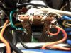
In the first picture of the Common Ground Modification discussion, there are two dangling fabric covered wires shown (coming from the switch?) and a green wire connected to the terminal strip where the earphone load resistors are attached. The green wire appears to come from somewhere on the bottom of the speaker/earphone switch?

In the second picture the green wire has been removed and the two dangling wires shown in the first picture have been connected to the terminal strip? One wire appears to be a red fabric covered wire and the other a brown fabric covered wire.

After a closer look at the first picture, it appears that the green wire was connected to a lug of the speaker switch where the Brown fabric covered wire was attached. One of the dangling wires in the first picture appears to have been connected to the Red fabric covered wire on the speaker switch terminal. So the two short dangling wires were removed and the red and brown fabric covered wires were moved to the 3-lug terminal with the earphone load resistors?

In the second picture it appears that a black wire has been connected to the switch lug that the Brown fabric covered wire was originally connected to. There appears to be a new white fabric covered wire connected to the top center lug of the speaker selector switch, or was it the same wire that was in the first picture but appears different due to slight lighting changes between taking pictures?

Were any other wires added to the speaker selector switch other than the black wire I spotted?

Joe
 
Omission on recent Rev A document of X-101C Mods

Today while wiring the LV Power Supply Board, I realized that I had left off a .22uF @ 50VDC film capacitor at the base of Q102, so that needs to be added to the schematic. It connects from the base of Q102 to ground, so it will not be difficult to add. The physical size needs to be small, so a low voltage rating helps with that issue. I had failed to order one, but had a suitable one on hand.

I am keeping track of any problems with the schematic or the BOM so that the document can be revised and released to the public again.

Joe
 
Modifying X-101 Earphone-Speaker wiring

I developed the following procedure to go about modifying the earphone and speaker wiring that Dave advised for the X-101C as part of his modifications and improvements.

First a word of caution: be careful in handling the speaker selector switch. The lugs of the switch are made of a rather brittle metal and they may break off right at the body of the switch if flexed too much. I did that today and broke one off of the switch in my amplifier. Remove solder from the lugs from which any wires or leads need to be moved or removed. Use solder wick and/or a solder sucker to get as much solder removed as possible before attempting to remove the leads from the lugs. I now will have to find still one more switch to replace the original speaker switch in my X-101C.

Here is the procedure:
1) Disconnect the orange and blue plastic covered wires that were at the mid-chassis two-lug plus ground lance terminal strip under T1 & T2 output transformers. Trace the two wires to their V5 and V6 destinations and disconnect them there. Remove and discard the orange and blue wires.

2) The common wires (black leads) of T1 and T2 previously were not grounded. These now need to be grounded at the ground lance of the mid-chassis two-lug plus ground lance terminal strip identified in step 1. Pre-tin the ground lance eye on the terminal strip. This will make it easier to get a good ground connection to the common wires of the output transformer secondaries. There is also a brown fabric covered wire on one terminal lug and a white fabric covered wire on the other lug of the terminal strip. Both the brown and white wires also need to be grounded to the ground lance. A short bare wire can be run from both lugs to the ground lance for this purpose. Solder all four wires to the ground lance of this terminal strip.

3) The end of R83 (25 ohm 5W resistor) that was grounded is to be unsoldered and lifted free of the ground lance it was originally connected to. The end which was disconnected is to be moved to lug no. 1 of the speaker selector switch and be soldered to it. Be very careful when dealing with the solder lugs of the speaker switch. The metal is somewhat brittle and can easily be fractured and broken from excessive bending. Use solder wick and/or a solder sucker to remove excess solder and carefully remove the extra green wire from the switch lug no. 1.

4) The end of R84 (25 ohm 5W resistor) that was grounded is to be unsoldered and lifted free from the ground lance it was originally connected to. The end which was disconnected is to be moved to lug no. 7 of the speaker switch and soldered to it. Be careful in handling wire removal and reconnection to prevent breaking the switch lugs.

5) Remove the ground wires connected to T1 and T2 brown (4 ohm) wires. The brown wires from both output transformers are to be connected to the 4 ohm lugs of the rear speaker terminal strips.

6) Add a yellow wire from the Ch A speaker terminal strip 4 ohm lug and dress it similar to the lead dress of the orange and blue wires previously removed. The destination of the yellow wire is near V5 and R 53.

7) Add a blue wire from the Ch A speaker terminal strip 16 ohm lug and dress it similar to the lead dress of the orange and blue wires previously removed. The destination of the blue wire is near V5 and R53.

8) Add a yellow wire from the Ch B speaker terminal strip 4 ohm lug and dress it similar to the lead dress of the orange and blue wires previously removed. The destination is near V5 and R57.

9) Add a blue wire from the Ch B speaker terminal strip 16 ohm lug and dress it similar to the lead dress of the orange and blue wires previously removed. The destination is near V6 and R57.

10) Swap the two 330 ohm 1W resistors termination points at the earphone jack. This brings the earphone jack connections into conformance with modern earphone standard connection practice. Ch A 300 ohm resistor connects to the plug tip and Ch b 300 ohm resistor connects to the ring (short sleeve) of an inserted ¼ inch phone plug.

11) Connect a 4.7K ohm resistor from the junction of Ch A 25 ohm 5W and 330 ohm 1W resistors and add a wire to the rear of the chassis and leave other end in the air near the earphone/speaker switch.

12) Connect a 4.7K ohm 1W resistor from the junction of Ch B 25 ohm 5W and 330 ohm 1W resistor junction (solder) and connect to the free air end of the other 4.7K ohm 1W resistor and solder.

13) Disconnect the Red Fabric covered wire from Lug 10 of the earphone/speaker selector switch. Slide a piece of 1/8 in. heat shrink tubing over the end of this wire and slide it back away from the end of the wire. Connect this end of the Red Fabric covered wire to the junction of the two 4.7K ohm 1W resistors and solder the connection. Slide the heat shrink tubing over this junction and shrink the tubing with heat from a suitable source.

14) Verify that the Red Fabric covered wire in step 13 is connected to Lug Y of the Center Channel Speaker Terminal Strip. Connect a 4.7K ohm 1W resistor from Lug Y to Lug X. Connect Lug X to the nearby chassis ground lance and solder all the connections just made.

The wires added from the 4 ohm and 16 ohm speaker terminal strips are the new negative feedback leads going to V5 and V6 circuits.

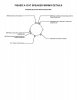
I am attaching an illustration of the rear of the speaker switch with lugs identified.

Joe
 

Attachments

  • X-101C Spkr Wiring Details.jpg
    X-101C Spkr Wiring Details.jpg
    30 KB · Views: 59
Last edited:
Op Amp Sub-Board

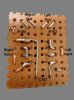
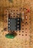
Since the Op Amp Sub-Board that Dave made is so small, I decided to do a drawing with the same parts identifications as those that we used in the X-101C Modification Schematic recently released. If someone is building this board this may help in the construction.

Joe
 

Attachments

  • Op Amp Subboard Back web.jpg
    Op Amp Subboard Back web.jpg
    49.9 KB · Views: 69
  • Op Amp Subboard web.jpg
    Op Amp Subboard web.jpg
    69.5 KB · Views: 69
  • Op Amp Installed web.jpg
    Op Amp Installed web.jpg
    79.2 KB · Views: 72
As far as resistor composition goes, here's my take:
These vintage pieces were all designed, built, and voiced around carbon comp resistors. Therefore, replacements should be of comparable materials for resistors that pass the audio signal. I typically use carbon film in an attempt to retain the designer's intent.

Newer gear designed, built and voiced around metal film resistors is equally good, just different.

For power supplies, I typically use metal oxide. For most everything else, carbon film. I've not had anything built with metal film that's required major surgery, and, for the most part, the vintage stuff has survived perfectly well with carbon comp, but some resistor's drift with age, moisture, and time - where the resistors in Fishers typically do not.

Conclusion: I, for one, attempt to stick with the designer's intent, so in these types of restorations, carbon film gets the nod. I'm fond of the takmans that Parts Express has.
 
Last edited:
Fisher Carbon Film Resistors

Don, I tend to agree with you. Dave has also commented about these issues too. When I first began checking some components in the X-101C I am restoring, I was surprised at how close the carbon film resistors checked against the marked values indicated. This is in spite of the unit being 50+ years old! This amplifier also had lots of top-side and underneath corrosion due to being a roach motel for part of its life. Even with the corrosion, the ground lances of terminal strips, tube sockets etc. still had perfectly good low resistance ground connections measured with my Fluke 8600A digital multimeter. I knew then that my job had just become easier.

High wattage carbon composition resistors and high values (usually over 100K ohms) tend to change in value over time much more than the lower values.

So far the only resistors I have changed in this unit were the ones that Dave said to change in his instructions.

Some time ago I had some issue with noise level (not hum) from my Dynaco PAS-3X preamp on magnetic phono inputs. At the time I was using it with an Onkyo M282 transistorized power amplifier. I did change a few carbon composition resistors in the low level stages in the PAS and it helped some but still was an issue. Later I discovered the primary problem was that the input of the Onkyo was a high impedance bridging input and needed a termination resistance to match better to the PAS output impedance. That made all the difference. Later on I built a ST-70 to work with the PAS and now have the best audio I have had in years.

Dave's measurements show that there is not much to be gained in changing to metal film resistors in this Fisher unit. No harm will be done either if a person wants to use metal film resistors. Many of my personal stock of resistors is now metal film type, but I still have a large number of carbon film types too. We are fortunate that we can still get thru-hole resistors and capacitors.

Joe
 
Don, I tend to agree with you. Dave has also commented about these issues too. When I first began checking some components in the X-101C I am restoring, I was surprised at how close the carbon film resistors checked against the marked values indicated. This is in spite of the unit being 50+ years old! This amplifier also had lots of top-side and underneath corrosion due to being a roach motel for part of its life. Even with the corrosion, the ground lances of terminal strips, tube sockets etc. still had perfectly good low resistance ground connections measured with my Fluke 8600A digital multimeter. I knew then that my job had just become easier.

High wattage carbon composition resistors and high values (usually over 100K ohms) tend to change in value over time much more than the lower values.

So far the only resistors I have changed in this unit were the ones that Dave said to change in his instructions.

Some time ago I had some issue with noise level (not hum) from my Dynaco PAS-3X preamp on magnetic phono inputs. At the time I was using it with an Onkyo M282 transistorized power amplifier. I did change a few carbon composition resistors in the low level stages in the PAS and it helped some but still was an issue. Later I discovered the primary problem was that the input of the Onkyo was a high impedance bridging input and needed a termination resistance to match better to the PAS output impedance. That made all the difference. Later on I built a ST-70 to work with the PAS and now have the best audio I have had in years.

Dave's measurements show that there is not much to be gained in changing to metal film resistors in this Fisher unit. No harm will be done either if a person wants to use metal film resistors. Many of my personal stock of resistors is now metal film type, but I still have a large number of carbon film types too. We are fortunate that we can still get thru-hole resistors and capacitors.

Joe
Joe, thank you for your efforts drawing up Dave's modifications, and also for all of your very helpful tips and photos of the speaker switch and the small circuit board markup. I've recently gotten ahold of my very own X-101-C, so I referred to this thread....better late than never. I have to say thank you to Dave as well! This thread is just AWESOME! I hope that when I get started with the restoration it will go smoothly. I'll be referring to your thread as well, Joe. I haven't looked at it yet, but I will shortly.
I believe that the carbon composition resistors that Fisher used were Allen-Bradley and the Deposited Carbon are German made. Not sure which company(Piher maybe?) If anyone knows I'd be very interested. The color bands and body on the Carbon Comp resistors in my Fisher units pretty much match the Allen-Bradley resistors that I have in my stock.(the colors and THICK layer of the color bands look very high quality and are pretty consistent) Anyway, I really like hearing how others feel about which type of components they like to use and their reasons why. I like to think that I'm using the proper parts when I'm replacing them so I listen to you guys for your advice.

John
 
I will post all of the changes made when finished.

The 100 ohm resistors on the output of the op-amps are primarily for stability. They do certainly add a degree of protection. But due to the extremely low output impedance of the unity gain configuration, placing any capacitance directly on the output of the op-amps is a sure fire invitation for instability. The resistors then act to isolate the output of the op-amps from any capacitive element in whatever is connected to the PO jacks, without unduly raising the output impedance in the process.

Dave
Dave, I've built and installed the op-amp in my 800c using Rev-09 of the 500-c schematic. It uses caps for both the input and output circuits of the IC. Will these cause problems? I would like to correct them before I fire it up. Thank you, Cory
 
The caps are necessary because the op-amp is operating from a unbalanced power supply source, so they need to remain in the circuit.

Dave
 
Dave, On the X101-C revised schematic, Can you please verify three component values? C117 says 610pf and C118 says 620pf. Is this correct? Also, C133 is of what voltage rating? Thank you sir!
 
Back
Top Bottom