• The move to the new server is done. There are some software and database maintenance updates in process. This has us passing the hat around to help out. We appreciate any donations. Seriously, even a dollar helps. The payment page may be found here - https://www.audiokarma.org/support.html

Improving the Fisher X-101C

View attachment 710862 View attachment 710863 View attachment 710864 View attachment 710865

Buzz couldn't resist this fun, complicated project.

Here are a couple of photos:

1. I like gluing modern doubler caps with JB weld to the old style phenolic cap spacers. One of the original doubling cap cans contained a 500V cap, which I migrated to the remaining can (I restuffed it with all new caps).

2. I stole the idea of installing 3-way binding posts on the two speaker terminals that I plan to use (i.e. 8 ohm and common);

3. I don't guess you can see it very well, but I simplified the Tape Head / Phono Hi / Phono Low input terminal strip into one RCA plug for MM phono only;

4. I had some reservations about drilling down into & removing the long terminal strip connecting to the bias and phase pots (the drill's torque forces can make a mess of things) so I decided to mount the three pots on a bracket. It's a lot more accessible that way, and it leaves LOTS of space for the 24V tranny & other stuff below.

More later, if Dave doesn't strangle me first . . .

And the little things.

Those bias/phase controls look to have the about same color plastic as the front panel push buttons.

I got to figure its not a coincidence knowing you Jon.

One of the things I appreciate the most about you Jon is your extreme attention to detail.

Frannie
 
Thanks, Frannie.

I'd like to be able to claim credit for the color match, but those are the OEM pots!
 
Thanks, Frannie.

I'd like to be able to claim credit for the color match, but those are the OEM pots!
Interesting. Mine are what appears to be "Black" in color.

Maybe I need to dust em off or get new glasses.

Now I want matching pots :)

See what you do to me!! :)

Frannie
 
I stuck the EFB circuit underneath the front control cover bracket. It ain't too pretty, but it's out of sight.

EFB install.jpg
 
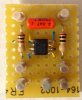
I put an OPA2134 high performance op amp on a perf board. My local supplier only had the part in a SOIC package, so I soldered some leads to it. In my old age, I had to use a microscope, and forgo the whiskey. :-)

Op Amp.jpg
 
Nice work Jon! If I may however, check the resistor on the right side of the op amp in your pic of it: it looks to be a 10 Ohm resistor, not 100 Ohms. The one on the left is correct.

Dave
 
This was the original design idea. I like it better than the gold version.

X101 PLATE.JPG
 
Last edited:
Trophy shop didn't follow my original instructions. I don't think it is any harder to make than the other.
 
Buzz, Do you have the part# for those speaker binding post's? I would like to add them to my 101-D. Thanks, Cory
 
Dave- Hopefully I can get some guidance from you? I have an X101-D that I totally reworked using the X-101C Rev C schematic. I have it on my bench hooked up to two eight ohm speakers and powered through my variac. I have audio through both channels, But when I put more than 72 volts a/c to it I get an oscillating horn sound through both channels. Is it possible there's a difference between the OPT's values thats causing this? Values of the feedback circuit? I'm stuck and pulling the rest of my hair out. It has the EFB circuit, OP amp and small power supply board installed. I also eliminated the phono preamp circuits and tubes because the sockets were destroyed and I was planning on using an separate phono amp anyways. Thanks for any reply, Cory
 
Hi Cory -- More than likely, the issue will be found in the output transformer connections. When you implement my power amplifier modifications in the X-101C, it requires you to:

1. Unground the 4Ω tap, and ground the Common output tap.

2. And most importantly, it requires you to reverse the primary leads to the output tubes. HOWEVER........

In the X-101D, the NFB is originally taken from the 16Ω tap, whereas in the X-101C, it is originally taken from the Common lead of the OPT. Therefore, if you implement my X-101C modification into an X-101D, then you WOULD NOT reverse the primary leads, or the amplifiers will oscillate, which is likely your problem. Reverse the leads, and let us know how it turns out!

Dave
 
Thats great news! Thank you Dave! I'll revert the primary OPT leads back to the way they were and report back. Give me a few hours. Thank you!!
 
That fixed it Dave!!! Thank you so much! One more question, Would it be beneficial ti use IBAM in this unit with tubes that are not closely matched?
 
With 118 volts a/c inputed I have 480v at CR1. The maximum negative voltage I get out of the EFB is -21.22 v. Input at each screen resistor is 416v. Do these values look close? The output tubes seem pretty hot.
 
The main B+ does rise due to reduced overall current draw under quiescent conditions. Output tubes should idle at 34 mA per tube. What are yours idling at? The original design was developed in an X-101C for AudioDon, which at the time used very good vintage tubes, so the bias range was based on those tubes. If you are using modern manufacture tubes -- particularly the new Tung Sol tubes -- then an adjustment to the circuit may be required. But see what the tubes are drawing first and let us know.

Dave
 
At idle V10 is .39v V9 is 245mv V8 is .41v and V7 is 318mv. Are my Slyvania tubes bad? Also, my bias pot is maxed out sending all the negative voltage it can muster.
 
Back
Top Bottom