• The move to the new server is done. There are some software and database maintenance updates in process. This has us passing the hat around to help out. We appreciate any donations. Seriously, even a dollar helps. The payment page may be found here - https://www.audiokarma.org/support.html

Infamous Kenwood KR-9600 in Protection mode.

Conspheracy

New Member
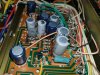
hey everyone, i'm new to audiokarma This particular receiver was my father's and he gave it to me as a house warming gift. It sat for a few years before I finally set it up with the original speakers in my home a few weeks ago. Upon the initial setup the relays did not want to close but after a few moments they did and the unit roared to life once again! It sounded great for the first week before the relays wouldn't stay closed in for more than a minute or two at a time until they wouldn't stay closed in at all. Thats when I started reading through as many posts as I could find regarding the various rebuilds and restorations on the infamous Kenwood KR-9600. I found the service manual PDF and have been using that for reference and trying to diagnose the possible issues this receiver may have. I decided to at least open up the receiver and attempt to troubleshoot/diagnose the issue. I'll post pictures of what I discovered.

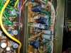
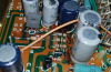
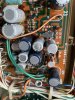
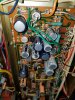
It appears the extent of the damage has been localized to the Power Supply A board (X00-1830-10) from leaking electrolytic cells causing corrosion to the following components.
Capacitors C1, C3, C6, C7, C8,
Resistors R4, R7, R8, R9
Diodes D1
Transistors Q6

I inspected all other boards and from what I can tell so far the only other damage is from the heat put out by the resistors on Power Supply B Board (X00-1860-10) so fingers crossed that the TA-200W's are in ok condition.

I've got some experience with desoldering, soldering in components but what i'm looking for is some insight on where to find the necessary replacements for all of these. While I understand this particular model is in no way, shape, or form ideal for a beginner, I do not know of any shop/technician nearby that has the knowledge to repair these receivers and I don't think i can afford to ship this out of state for repairs. Thanks in advance!
 

Attachments

  • kenwood 1.jpg
    kenwood 1.jpg
    139.8 KB · Views: 127
  • kenwood 2.jpg
    kenwood 2.jpg
    136.1 KB · Views: 122
  • kenwood 3.jpg
    kenwood 3.jpg
    140.2 KB · Views: 116
  • kenwood 4.jpg
    kenwood 4.jpg
    143.6 KB · Views: 116
  • kenwood 5.jpg
    kenwood 5.jpg
    115.5 KB · Views: 114
Register to hide this ad
Source components from a reliable vendor like mouser or digikey.
Avoid ebay and others.
The leaky material may be component glue, in any case it needs to be cleaned up. C7 looks very sick.
Recapping the power supply appears unavoidable. Yeah, it's a big task, you will need to be methodical.
Focus on power supply as stage one, only when working ok decide if you do more. Not a bad idea to
measure power supply voltages as a baseline.
 
Source components from a reliable vendor like mouser or digikey.
Avoid ebay and others.
The leaky material may be component glue, in any case it needs to be cleaned up. C7 looks very sick.
Recapping the power supply appears unavoidable. Yeah, it's a big task, you will need to be methodical.
Focus on power supply as stage one, only when working ok decide if you do more. Not a bad idea to
measure power supply voltages as a baseline.
I have measured power supply voltages but did not record any of the data for either power supply board. From what I could tell the B board appears to have "normal" voltages, the A board, as you can tell, had multiple voltage issues. I plan to work on this slowly and replacing the above listed components first before going any further. I have seen some upgrades in other threads that i would like to eventually perform as i get more comfortable working on this receiver, such as upgrading the resistors on power supply B, as well as the 4 large electrolytic cells for the amp boards. Id like to stay as close to original as possible though so I dont plan to upgrade to LEDs. I appreciate your input and definitely plan to document the restoration project.
 
Yeah, I'd say at least one capacitor has blown it's guts out, and that means the others are not far behind.

Download the service manual (or buy a paper copy) and start replacing those electrolytic caps. All of the caps on the power supply board should be low impedance caps, you don't need audio grade (low noise) caps in the power supply, low equivalent series resistance is more important there. New ones will be smaller even if you get ones with higher rated voltage (which I recommend, one step up). At the very least replace the swollen one, it's obviously shot!

Also replace any corroded resistors or diodes.

Check all the resistors and diodes on the power supply boards for correct values and replace any that are bad, particularly Zener diodes which have a tendency to fail as a short, very hard on capacitors. Once you have new capacitors installed, it's time to hook up the dim bulb tester and start looking for bad semiconductors -- limiting the current will prevent any damage to expensive or impossible to obtain outputs.

Typical failures that prevent the speaker relay from closing are shorted diodes, shorted power regulation transistors, open resistors, and way out of spec capacitors (and you have at least one.....).

It's quite likely that it won't come out of protection on a low wattage bulb in the DBT - I use a 40watt for troubleshooting and larger amps just won't get enough voltage on the rails to close the relay, but you can always use a higher wattage bulb (NOT an LED bulb) when you are at that stage. Get all the power supply issues sorted out first.
 
And my $0.02, if the amp has been unmolested until now, be sure to use replacement part values that are what's actually on the circuit board if there is any discrepancy with the schematic or parts list values.
 
I definitely do not want to damage this receiver more than it already has been because of its age so i'm working on a plan to tackle my issues. I'm hoping this isnt going to be one of those, just the tip of the iceberg type projects but i'm sure there will be other issues that arise from this. Currently I'm working on finding the correct electrolytic capacitors to replace the damaged ones, as well as the resistors, diodes, and the bad transistor at Q6. I've downloaded and printed out the service manual for reference that i'm working on becoming more familiar with. As for my experience level, i've soldered sockets and resistors into a few automobile ECU's with instructions on which pins to desolder. I am fully aware this is one of the more challenging receivers to attempt repairs on and while I would love to do a full rebuild/restoration on this unit to truly unleash its full potential in the modern age, I know I'm not even close to competent for such a task.

Going forward from here i'll make sure to go back and start writing down voltages for the Power Supply A Board (1830) considering that has the most noticeable damage. I'll also get voltages on the relay board, amp boards, power supply (1840) and power supply B (1860). As of now I only plan to replace the components listed in my initial post. I've also read into a few upgrades that i've been considering down the road if this 1830 board is my only issue. The upgrades I had in mind are to replace the resistors on 1860 with an aluminum cased 75 ohm 25W resistor and replacing Qr1, Qr2, as well as replacing the large electrolytic cells if those are showing any signs of leakage.

Currently I'm working the night shift and am about to go on vacation next week so I should have some decent time coming up to get all the voltage readings as well as hopefully find all of these replacement components, which is honestly my biggest struggle right now. I've never bought anything like this before so I'm fairly lost in terms of what brands are decent, what rated voltages I could potentially upgrade the capacitors to, etc. Thats one of the reasons I made this thread, get some more insight on proper components to buy and to hopefully speak with others who have attempted similar restorations. I appreciate all of your insights and the knowledge you all have shared with me so far and look forward to having more conversations regarding this incredible receiver and how to get it back to its full glory!
 
I am fully aware this is one of the more challenging receivers to attempt repairs on and while I would love to do a full rebuild/restoration on this unit to truly unleash its full potential in the modern age, I know I'm not even close to competent for such a task.
Sir? Perhaps you should start on something less complex and less risky. I've been a member since 2012 and was reading about a year before I joined. I've had some tech school and practical experience.. before that even at an early age I was messing with gear. Me and many other regulars have read many similar threads exhibiting as much as enthusiasm as you simply fade away.
Just read the initial OP's post, it's a list of op failure post titles by people who didn't know what they were doing.
https://audiokarma.org/forums/index.php?threads/wow.915320/
 
Sir? Perhaps you should start on something less complex and less risky. Me and many other regulars have read many similar threads exhibiting as much as enthusiasm as you simply fade away. Just read the initial OP's post, it's a list of op failure post titles by people who didn't know what they were doing. https://audiokarma.org/forums/index.php?threads/wow.915320/

I've got no problem admitting that i'm not 100% certain what i'm getting myself into with this project but I am more than capable of learning what needs to be done first in order to get this unit repaired in a cost effective way even if it takes a few months before actually desoldering the first damaged component. Not to be rude but do you think its a possibility that the many new threads of similar enthusiastic individuals, such as myself, that you speak of became discouraged when they were probably told the same thing you told me?

I appreciate your concern and understand that there is a huge potential of failure for beginners when taking the shotgun method in replacing the damaged components. Which is why I made this post to gain more knowledge from experienced individuals BEFORE I attempt to do any repairs to the damaged components. I realize there are potentially other issues with this unit that I may not be aware of at this moment but I will cross that bridge when I get there and hopefully be able to receive some help from more individuals such as yourself who recommended building the dim bulb tester, thank you by the way. Currently, my only goal is to repair the obvious damage with the correct components so that I can continue to diagnose and troubleshoot any other possible issues with this receiver that may arise after the fact. If this project takes me until Christmas or next Independence day then so be it.

In the AM when I get home from work I plan to measure and record the voltages of each board, I also plan to check the voltages of other components on the power supply 1830 board to ensure there is nothing else damaged. The next step will be continuing to determine suitable replacement capacitors, resistors, diode, and transistor, then after I have all replacement parts is when I plan to begin the actual process of desoldering, cleaning the board, and replacing with new components. After that I will again measure and record voltages to compare the changes. Hopefully there will be more input from individuals with more experience than myself to help me out and if not then I will just need to continue to learn more about these receivers before I continue.
 
Well, i do encourage you to go on. I am NOT a tech, by any means, i'm a mechanic. But, had success recaping, and fixing minor issues on maybe 12 receivers, pre-amps, power amps, tuners and integrateds. The only one that wasn't successfull was a Kenwood KA-701 that i bought as a non-working unit. It works now, but has 2 problems that i never could fix.
All in all, i did pretty good so yeah, go for it!!!.
 
Well, i do encourage you to go on. I am NOT a tech, by any means, i'm a mechanic.
All in all, i did pretty good so yeah, go for it!!!.
I'm a power plant operator and self taught mechanic. Ive got experience with desoldering and soldering in new/replacement components. My biggest issue is just trying to find the correct components to replace the damaged ones. I've never bought anything like this before so I'm struggling to know if what I would be buying is correct
 
Mouser and Digikey both have very comprehensive catalogs, but it may take you a while to figure them out, they are a bit complex if you don't know your way around electronics, and even if you do and it's been 40 years!

For the electrolytic caps, in the power supply you want to select passive components on Mouser, then aluminum electrolytic capacitors, then radial leaded caps. That will land you on a page with a million options, but that's where you can select low impedance capacitors and then the voltage and uF rating you need for each one.

I make a list from the service manual (if possible, Sansui doesn't list them except in a non-obtainable addendum) and figure out what I need, put them in a spreadsheet with the capacitor number, the copy that data and sort by voltage and uF rating. That lets me count up what I need for each size. I then look them up in the on line catalog and note price each and price in tens (or 25s) as it can be cheaper to buy 10 than six. Plan to get one extra for each rating, you might miss one or fry one or lose one.

For that beast, I'd don one board at a time, only difficulty will be shipping cost. Mouser is $7.99 per shipment in the quantities we use for one amp, you don't want to make too many orders, but you also don't want to buy too many extras.

Do some searching here on AK for appropriate main filter caps, I don't know off the top of my head what will work, I can only state that the originals are highly unlikely to be available. For some reason, big filter caps don't seem to stay in production very long, or they were custom orders to start with.

T'were it me, I'd get main filter caps (which will cost more than the rest of the caps put together) and any caps and suspect transistors on the power supply board and start there.

Won't hurt to select what you think you need and post the list with catalog numbers here before ordering, you will get plenty of help making sure you have what you need.
 
Welcome to Audiokarma!
Buy parts from reputable parts distributors like Mouser, Digikey, Arrow, etc.
Auction sites are a poor source for parts, too many fakes, forgeries or 'reclaimed' parts.
Don't bother trying to replace with New Old Stock, modern parts are better quality. There are many lists on AK with part replacement suggestions.
 
Not too sure if anyone will respond back to this thread but figured I'd start to update again. Life got very busy for me shortly after making this thread and the project to restore this unit got pushed to the wayside with home renovations and work. Would really like to start this project again as most of the renovations have come to an end and I would like my family to be able to enjoy getting some use out of this unit.

Currently I've got replacement capacitors and diodes for the power supply board ready to be ordered but im having some difficulties trying to identify the resistors and compare them in the parts list. The service manual only lists four resistors and the four I have listed for replacement are not among that list. I'm attempting to identify the colors and replace the resistors that way but the pictures of the replacements on Mouser dont have the same colors (is this because they use a stock image for their resistors?) One of my struggles is identifying the top resistor in image Kenwood 2, it appears to be two blue lines but they are different colors, a dark blue and a sky blue?

The other issue im running into is finding a replacement transistor for Q6 - 2SA733. When I search for similar transistors it comes up with KSA128YTA. I found this thread https://audiokarma.org/forums/index.php?threads/transistor-substitutions.688515/ which shows a few possible replacements as well. KSC945CYTA & KSA1013YTA were the replacements i was looking into but im not 100% certain which would be suitable replacements.

I appreciate any further input from you all and look forward to hopefully getting some time to start replacing these components. Thank you.
 
I appreciate any further input from you all
Welcome back!!
First off I'm not sure if you need to replace those resistors perhaps just clean up the cap guts as corrosion may not have set in.
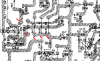
I took a snippet of pdf page 22 showing the solder side view and components referencing D1 (that also may check okay and easy to test in circuit. your dmm will show only resistance or continuity one way and zero the other. Resistors would need to lift a leg and measure))
I assume you tested transistor Q6 in question??

upload_2021-8-31_11-56-22.png

upload_2021-8-31_11-57-36.png
 
Welcome back!!
First off I'm not sure if you need to replace those resistors perhaps just clean up the cap guts as corrosion may not have set in.
I took a snippet of pdf page 22 showing the solder side view and components referencing D1 (that also may check okay and easy to test in circuit. your dmm will show only resistance or continuity one way and zero the other. Resistors would need to lift a leg and measure))
I assume you tested transistor Q6 in question??

View attachment 2330225

View attachment 2330226
Hard to get a good picture but one leg of Q6 is toast and measuring no voltage. I got out of work this morning and went upstairs to verify a few things with the receiver. Upon plugging it in to check voltages the most bizarre thing happened, the main relay clicked on and the unit was able to play music for the first time in over a year.

Ordered the capacitors, resistors, transistor, and diode this morning and they should be in Thursday. I believe I may have missed a capacitor that needs replacing and will need to make a second order for parts, C22 appears to have some discoloration on it but when I get the time to pull the board up I’ll check voltages on the underside of the board to verify.

The plan as of now is to get a decent soldering iron, solder, some good electrical flux, as well as some deoxit and start methodically taking this apart for repairs and cleaning.
 

Attachments

  • B0A0DD2E-B6FF-4224-89E8-0D8342898B29.jpeg
    B0A0DD2E-B6FF-4224-89E8-0D8342898B29.jpeg
    142.1 KB · Views: 29
Back
Top Bottom