• The move to the new server is done. There are some software and database maintenance updates in process. This has us passing the hat around to help out. We appreciate any donations. Seriously, even a dollar helps. The payment page may be found here - https://www.audiokarma.org/support.html

Infinity Kappa 9's - Goes against core design principals?

Bradmich

New Member
Hi Audio-heads!

Just got my hands on the original set of Kappa 9's I bought new in 1992. It's a long story, however the previous owner traced them back to me and the vintage audio-head that I am; I had to buy them back.

Anyway, here's the bend...

As its been posted correctly, these speakers are amplifier current heavy, (really heavy) and are not all that efficient (calling BS on the published 102db SPL rating- more like 86 SPL). After disassembling them, I can see why, there's a serious ton of crossover overhead. Back to that challenge later.

In addition to the heavy overhead of the crossover design (and impedance dip to 1 ohm), is the close proximity and single plane of the crossover inductors on the back-side of the PC board. This is a huge design no, no... See: http://troelsgravesen.dk/coils.htm.

I've built/designed plenty of crossovers in the past and have made that same inductor mistake. I then properly placed/distanced them correctly as well as put then on different dimensional planes....and OMG! what a difference!, it's NOT subtle, it's huge (All of the mushiness disappears, especially at volume). Even back in 1992 (I owned an audio store in those days so I could do a ton of comparison), they always seemed to blend/saturate a bit funky to me- which has me thinking this is the root cause.

That leaves three choices for restoration:
1: Just replace caps (better than existing- but does nothing for the inductor or current-heavy issue)
2: Build new boards and properly arrange the coils (Fixes mushiness above, but not the current-heavy)
3. Design a new crossover (with more efficient design and proper coil locations- but it's NOT the OEM design)

Other Speaker design Weirdness

As pointed out on other threads, the cabinets are by no means sealed.
1. The base-plate holes are not sealed
2. The factory fascia fabric overlaps all of the drivers (there is no solid rubber-to-speaker-to-cabinet seal).
3. The woofers (I think there are the original factory drivers?) have multiple 1/4" air holes around the cone just outside the voice coils (Which are covered by an air-permeable dust cap).

All of these sealing issues can be addressed - but should they?

I Love that the Kappa 9s leverage ribbon drivers and filled the mid-range gaps with domes - it's a cool design - but maybe bad execution? I also hear the logic that; "Infinity engineers designed it that way.", but again not so sure I should blindly follow that legion when it seems to go against core design principals? (Engineers also designed the Titanic and Yugo).

I'd love to be proven wrong as it would make restoring these much easier.

Thoughts?

Thanks! Mark
 
Register to hide this ad
Do you think you can pull it off? Re-engineering and redesigning the crossover is no easy task, especially on a speaker of such complexity...


If you can do it, I would go all out and do what you feel to be the right way.
 
Looking at the Kappa 9 schematic, it looks like the dual 12" woofers are wired in parallel to each other. That probably causes the low impedance dip in the bass. You could try rewiring the woofers in series. That should improve the impedance, but you'd have to change the woofer crossover values. Inductance generally doubles and capacitance halves when impedance doubles. Plus, the other drivers would need to be rebalanced to bass level changes. The L-Pads might have enough range. If not, you could play with the various resistors in circuit.

Good luck.

Oh yea, another thought. Study the Gamma/Delta crossover schematic. The Kappa 9s and Gamma's are very similar in design, other than the Gamma uses planar mid drivers instead of dome mid drivers. Compare the 2 crossovers. Maybe the Gamma's do things defferently, that don't cause the impedance dips if the 9s?
 
Last edited:
Wiring the woofers in series cuts bass output? You lose a few dbs. That would mean you would have to modify the rest of the crossover to accommodate the db loss.

It's a classic speaker and yes it has it flaws. If your going to go through alot of trouble to reengineer them. Post your findings so others can copy them.
 
Looking at the Kappa 9 schematic, it looks like the dual 12" woofers are wired in parallel to each other. That probably causes the low impedance dip in the bass. You could try rewiring the woofers in series.

Re-read your schematic--the woofers are wired in series. There is an inductor that basically shorts the woofer circuit that results in the low impedance dip. There is also a switch on the back panel of the speaker for "normal" or "extended" mode--all it does is add a 1 ohm resistor to the woofer circuit in normal mode to make them easier to drive, but it does kill bass response.
 
The schematic, from Infinity-Classic, is a bit confusing. It doesn't show the wiring to both woofers. Just to one. Usually, when in series, two woofers are depicted, which lead me to believe that they were in parallel. Regardless, that ruins my suggestions.

Also, I'm aware of the circuit layout, and the impedance woofer switch. Though, I do wonder about the inclusion of the resistor, if it is as harmful to performance as you suggest? Plus, why only a 1 Ohm resistor? Did it really do that much to improve the impedance dip? Perhaps a 'better' resistor would improve the use of the extended mode switch? A Mills or a Mundorf resistor might be less harmful?
 

Attachments

Though, I do wonder about the inclusion of the resistor, if it is as harmful to performance as you suggest? Plus, why only a 1 Ohm resistor? Did it really do that much to improve the impedance dip? Perhaps a 'better' resistor would improve the use of the extended mode switch? A Mills or a Mundorf resistor might be less harmful?

Unfortunately, I don't have all the answers for you. I can tell you (from personal experience) that with the switch engaged to include the resistor, it does have an audible negative effect on low-end performance. As for a 1 ohm value being that much of a mitigating factor regarding the impedance dip, IDK, but I would guess that by increasing the minimum impedance by ~100% (from just under 1 ohm to ~2 ohms) would be significant to amplifiers that are already on the brink of shut-down when presented with loads below 4 ohms.

Again, IDK if there is a "better" alternative for the "optional" resistor in the woofer circuit. All of the ones that I have owned and/or restored for others have been in or returned to OEM configuration. I have seen some real "hack jobs" by people trying to "fix" what isn't broken--just pay the money and buy appropriate amplification.

It is rather common to find the woofers re-wired incorrectly, since most people assume that they should be in parallel (as is the "norm" with many other speakers using dual woofers). The woofers get pulled for a re-foam, and then get re-installed incorrectly in parallel configuration.
 
Last edited:
Thanks everyone for the feedback thus far!

Update:

I’ve been studying the infinity crossover schematic all day at work (was driving me crazy), trying to make sense of the design. IMHO...Engineers or not – it’s terrible...really, really terrible.

Many examples; the (4) 500uf caps (2,000uf) on the woofers for sub frequencies-huh? Never seen that before; the 15mh coil (L12) -what causes the sub-1ohm load; the integration design of the L-pads creates a varied load = varied crossover points; Wonder Caps – serious?; Cheap NPE’s; Use of magnetic inductors (not all air); proximity of air inductors on the PC-board; etc. etc. Think about it - who designs a crossover where the requirement for the amp is that it will accept a nail across its outputs?

What I do love is the actual driver(s) design, use of 12ga wire and soldered connections throughout. From a build perspective, they are right-on! Better than you see even in some current $10K plus speakers on the market (I have a set so can attest to that – was surprised how marginal they are once you open them up).

No, I'm not a super-seasoned engineer but this design goes against soooo many basic principles. All I can think of is; someone (thinking intern) was told to design a crossover, then kept over compensating by adding parts to address other flaws - Dunno, don’t care, doesn’t matter. In software, we call it, Frankenware.

My gut says that the K9s are being seriously handicapped; all of us are missing out on their true potential. In any case, going to build some from scratch- will keep everyone posted (with pics) - may be a few months. Proof is in the sound.

My audio reference will be a sub-master 2Track/15ips tape from ABC records, (I’m a 70’s analog guy) As a side note, until you’ve heard tape, you don’t know what you’re missing (it’s freakin incredible!) - better than my SACD or DSD by a longshot... but yea, tape like marriage, is a long-term commitment...requires lots of ceremony (loading/rewinding) before you can listen to a single song and very slim, slim pickings :)
 
I doubt they told an intern to design a crossover in a (adjusted for inflation) $3,000 MSRP pair of speakers.
And if you could afford these speakers you could probably afford an amp that could drive endless current into a brick.
NPE's are used for larger values because these are after all speakers sold to make a profit, electrolytics are pretty standard, as well as iron core inductors. Air core is just ridiculous at that high of millihenrys. And there's absolutly nothing wrong with having L-pad's, they can be quite handy.
You mention you've never seen a large high pass on woofers, you think Infinity put a large, expensive capacitor in the circuit for no reason?
Trust me - I'm not saying these guys were perfect or that this crossover is anywhere near perfect, but most of your points are just not valid.
 
C19 and L12 form a very low frequency high pass filter that is probably designed to have
some peaking to boost the low end before roll-off. If you enter 2000uf and .015 Henries here:
https://www.pad2pad.com/calculators/l-c-resonance/

the resonance comes up as 29 Hz supporting the theory. The added resistance lowers the Q
and the amount of boost.

It would be interesting to measure the DCR of the woofers to see what the woofer impedance
would be if you removed that network.
You could remove C19 and L12 and just add bass boost at line level to get around the impedance dip.

This is known as a primitive transformer network, and if you are going to get voltage boost
the penalty is an increase in current/lower Zin. Get a monster amp if you want to run it as is.
Adcoms are known to do low Z loads well as a budget solution.
 
Last edited:
Hi Pete, Excellent feedback and makes complete sense, many thanks!
It would just become a plane ole 1st order which I think is OK and eliminates the need to drive them with heavy current.

Looks like the Mid-bass and Midrange are 3rd order butterworth, but again the L-pads (as currently wired) shift the crossover points, so thought was to wire it across the speaker load to keep the impedance constant otherwise, plan was to keep all other design as is.

Going to replace the Iron core inductors with Air (As you know, Iron-core’s saturate and can sound nasty) and properly plane/space all of the other inductors to mitigate any possible cross-talk.

Get rid of the useless “Wonder caps”

Eliminate the breakers altogether

Replace all caps with Solen or something a bit less costly

For the cabinet; was going to completely reskin in cherry (including fascia and replace toothed sides), then finish in 12 coats of piano lacquer. Seal it properly (The holes in the woofers have me scratching my head – making it neither a completely sealed nor open design (More weirdness?) – but going to seal them anyway along with properly sealing all of the drivers and bottom plate holes)

It’s a good winter-long project...
 
Are you able to measure the input impedance of each of the drivers vs. frequency?
If not how about the DCR?
 
<snip>
No, I'm not a super-seasoned engineer but this design goes against soooo many basic principles. All I can think of is; someone (thinking intern) was told to design a crossover, then kept over compensating by adding parts to address other flaws - Dunno, don’t care, doesn’t matter. In software, we call it, Frankenware.
<snip>

I don't think Infinity had an intern designing crossovers in any of their speakers. My recollection was that their crossovers were much more complex than most other manufacturers of the day, especially in their higher end systems.

From http://www.hifi-review.com/153732-infinity-kappa-9.html:

"Nonetheless, in designing the 9 Kappa, Infinity took advantage of the lessons learned in building the $45,000 IRS Series V and the Beta, Gamma, and Delta group; as a result, the 9 Kappa introduces new driver and crossover technology at a much more affordable price."

Arnie Nudell was still at Infinity, and he probably still had a hand in crossover design. This is the guy that designed the servo controlled feedback system more than a decade earlier. I don't think he was a hack, and I can't imagine him putting up with somebody kludging something together.

Anyhow, looking forward to see what you come up with.

bs
 
For the crossovers, I think you should do steps 1 & 2, and listen to the results. Then, if you wish to go further, try your alternate design, but keep the originals intact, for comparison, and for re-conversion to original if desired.

My hunch regarding driver and cabinet sealing is that it is an attempt at 'aperiodic' loading, kind of like the slots in the big Altecs and similar old designs, before Thiel & Small modeled sealed and ported enclosures. This time, I believe it was done in order to have a slender cabinet profile, to save on materials and avoid or lessen the 'giant speaker' WAF issues. That is just my theory, but such slender, low volume cabinets are unusual for big woofers, let alone two of them.

There is no reason to put speaker designers on pedestals. Excepting Paul Klipsch, Peter Walker, Ed Villchur, and Jon Dahlquist, of course. ;)
 
This does not apply to this thread since it does not employ Watkins woofers but it speaks
to Nudell's engineering skills:

The full post from rec.audio.opinion by Bill Watkins:

Trevor, I believe it's time I explained what happened
here. My dual-drive woofer works so:
A second voice coil (vc-2) is wound over the main voice
coil (vc-1) in the woofer, this second coil having a
single layer and very low impedance. Now vc-2 would
normally have an impedance too low for safe operation.
However around fundamental resonance the impedance of
_any_ coil will ~triple. Now we activate vc-2 _ONLY_
in the region of fundamental resonance (around 45 Hz)
and it rises to ~8 ohms or so (being ~2.5 in the
first place) which is safe. This is accomplished with
an LC circuit tuned to 45 HZ and with the Q of the LC
circuit adjusted to provide the response shape and
impedance desired. Please note that the exact value
of vc-2 and the characteristics of the LC circuit give
_COMPLETE_ control of the impedance. The benefit of
the dual-drive may then be taken in extended bass or
higher efficiency in a given size box, or a smaller
box for a given efficiency or bass extension.

Now I set the parameters of the original QLS-1 in a
prototype and shipped it to Infinity. It had a minimum
impedance of 3.2 ohms, acceptable for a 4 ohm speaker.
At that time we were operating a retail store selling
Infinity. Our first shipment of the QLS-1's arrived,
we tested a pair and found the impedance to be
~1 3/4 ohms from ~50 - 80 HZ. Now, the fun begins...
Mr. Nudell wanted a spec down to 20 HZ, he got to
18, as I recall, by adding ~35 grams of mass under
the dust cap, _BUT_ he did not re-tune LC to the
lower resonant frequency, leaving vc-2 operating
somewhat above the new fundamental resonance, and
creating a low impedance in that area. My name
was already on the royalty agreement, which had no
stipulation to cover such... I did voice my
disapproval to no avail.

If you check, you will find our WE-1, built and
marketed by _my_ company had no impedance problems,
and neither did thousands of other speakers we
built have any impedance problems. Perhaps this
makes things clear for the technical people here.

Bill Watkins
 
Wow!...thanks!, absorbing all this.


Hi SQLSavior (aka PostgreSQL killer :)
I hear you on the cabinet venting, but it does not make sense to me (as least how they did it). As you know, it's not really ported, it's just "leaky" - None of the drivers are fully sealed against the carpet-like fascia, small leaks everywhere, there are (4) 1/4" holes in each woofer covered by the dust-cap, etc. Like I said it's neither sealed nor fully open, just lots of weirdness. Since I'm reskinning the entire cabinet in Cherry (Including the fascia) which addresses the drivers, I thought I might as well finish the sealing process + address the woofer holes.

Hi Pete
Yes, I have a sweep generator and can test impedance- was thinking of using a Zobel circuit and call it a day.
Yes, I saw that company too. I'm a DIY kinda guy but I do really like what they did in principal- going to do a hybrid of that.

PS:
I was just being facetious when I said they likely an intern develop these - I'm in software and we always blame/shame the interns.
I've seen this approach in SW code development 100's of times, where the engineer(s) (very good engineers) went ballistic; adding a Sh&t-Ton of unnecessary overhead - IMHO, on the surface, it's how these appear to me - Think of the game, Mouse trap.

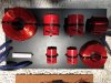
My plan is to keep the old crossovers 100% intact and build new from scratch, will be much easier and when I sell them (which I will - I'm in more for the challenge) - the buyer may desire those. Here's a pic of the ones I built for for my restored ESS AMT1b's. Granted the K9's will be significantly more complex- but still no big deal.

Again the proof will be in the sound- going to only do one first; then compare and contrast.
Will keep everyone posted with Pics and Spectrum analyzer results.

Thanks Gents!
 

Attachments

  • ESS Crossovers.jpg
    ESS Crossovers.jpg
    133.1 KB · Views: 90
If we could get .zma files I could simulate the XO frequency response in Xsim.
I think that the flat panel speakers will have minor variations from the DCR, the
others we'd want peaks and a few measurements along the rise due to Lvc.
Best to do both sides in case any of the drivers have been damaged or drifted
over time.

If these were mine, I'd probably keep the passive bass boost circuit but try to keep
the impedance dip around or above 2 ohms. I'd only use the speakers with high
current amps that do not have output protection that might falsely trip. It would help
to know the DCR of the woofers. If you wire them in series, the voltage sensitivity
will drop and you won't be able to achieve the same SPLs without far more rated
8 ohm power.

The Adcom
GFA555II is a good choice but you have to up the rail fuses and I'd drop the rail
voltage if planning to keep them in the system. A variac outside of the amp would
do. There is no active output protection, just fuses, and 8 large output devices are
used per channel. An amp with output protection will have it trip and sound very bad.
 
Last edited:
Back
Top Bottom