• The move to the new server is done. There are some software and database maintenance updates in process. This has us passing the hat around to help out. We appreciate any donations. Seriously, even a dollar helps. The payment page may be found here - https://www.audiokarma.org/support.html

Infinity Kappa 9's - Goes against core design principals?

About the leaks, sealed box systems need a small leak, AR discovered this in the
early days and it does not harm the system response. The system acts as a barometer
when there is no leak.
On the other hand, a sloppy leak will often chuff on high bass excursion so it might be
best to seal them up, then provide a small hole if needed on the back or bottom.
 
Hi Pete,

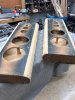
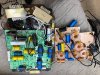
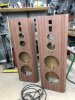
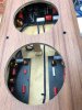
Thanks again- Will definitively consider those options: starting on the cabinets first - See pics.

As a sidebar- back in the day when I owned an Audio company (80's) we focused a lot on car audio as well: we were the primary systems designer for Lamborghini and just about everyone's show-car; Panasonic, Pioneer, Sony, Car&Driver, etc. Our competition car even had a compander/expander, noise gate, 24db/oct Linkwitiz/riley crossovers, time-aligned drivers - Was nuts! Man, that was freaking fun back then- kinda doing a "relive the moment" at a much smaller scale.

You're feedback is making me open my old tech training books :)
 

Attachments

  • K9 in the Raw.jpg
    K9 in the Raw.jpg
    73.5 KB · Views: 164
  • K9 Original CO.jpg
    K9 Original CO.jpg
    145.8 KB · Views: 164
The LC circuit ahead of the two woofers was called LC tuning of the woofers to overcome the problem of high impedance at resonance without resorting to Watkins dual voice coil. I have seen Infinity promo material for the Kappa 9s that talk about computer aided design to carefully tune the woofers with the LC circuit. The woofer circuit is identical to the non servo IRS Delta and indeed use the same Woofers as the IRS Beta without the accelerometer. I have the IRS Beta and numbers of the back of the woofer match 902-3054 and are IMG injection molded graphite cones. The crossover to cut the highs and hand over to the midbass is different; in the Kappa 9 it is 1st order just a 12.5mH inductor for nominal 80Hz while in the Delta it uses a 2nd order 6.5mH and 250uF cap to cross to the LEMIM at 130Hz. In the Delta the two woofers are clearly shown as wired in series while the schematic for the Kappa 9 does not specify if they were supposed to be in parallel or series. Given that the LC tuning is identical and the 12.5 mh inductor in series with the woofers would give a 100Hz corner frequency for a load of 8 ohms is indicative that the intent is for the Kappa 9s to be in series. Could be wrong.
My guess on how the LC tuning is supposed to work:
At resonance in the box, the impedance of the woofers would be maybe 3x their minimum and purely resistive so about 24ohms. Above resonance the load becomes capacitive as the impedance drops to a minimum before taking off again due to Le of the voice coil but here this is not a factor here because they are being crossed over at 80Hz. Below resonance in the box the woofers presents an inductive load as the impedance rises to the resonant peak.

The problem is the same problem addressed by the dual Watkins drive solution; amplifiers are trying to be voltage sources so as R goes up power goes down ( Vsquared/R) so bass power into the speaker goes down at resonance.
By putting the 2000uF cap in series with a 15mH inductor across the amp, that circuit by itself will measure the series resistance of the inductor resonance calculated here as 29Hz. If that inductor real resistance is 0.1ohm and the amplifier can drive 10 amps into the 0.1 ohms that would be delivering 10watts. At the same time the voltage across the inductor would be leading the current by 90 degrees and equal to Ldi/dt = .015H * d{10sin (2*pi*f* t)}/dt = 0.015*10*2*pi*29Cos2pi*t = 27.33 peak voltage. The Capacitor would have a corresponding lagging voltage of 27.33V which would be 180 degrees out of phase with the inductor.
The amplifier is putting out only 1 volt into the 0.1ohm resistive load but the inductor would have 27v to drive the woofers at 29Hz.
So LC tuning is a way for the amp to pump energy into a resonant tank to power the speaker with higher voltage at higher impedance associated with the speaker going to it's Fs.
All of this has to be fine tuned so the tank circuit aligns properly with the speakers resonance in the box and I am not sure the optimum effect is for them to coincide when calculated separately as the LC tuning affects the resonance of the woofers and vice versa, so here is where computer simulation comes in. If you get it just right then you end up with a sliding resonance where the 15 mH inductor and the woofer load interact to keep the impedance close to a goal of 3 ohms . Of course things go out of alignment with age spiders and surrounds stretch, box leakage and foam gaskets under the speaker compress and the mechanical and electrical Q of the woofers in the box change as does the 2000uf Cap value.
Very clever of Mr. Nudell, he was an advocate of class D for bass. I would say and if you could drive the woofer section with a high current capable amp like a class D amp then it would only be responsible for 20Hz to say 160 hz (an octave above crossover) .
If you read Arnie Nudell's response to the review of the Kappa 9 in The Absolute Sound, it is clear that he was quite proud of the 9s.
The Question is whether the bass you will hear will be accurate as was in the recording or just boosted by some technical trickery. Well we know that you have to pump energy in maybe one cycle before the energy is there to use but that is the same as bass reflex and passive radiators. SO it appears that if you can survive the low real resistance a some frequencies then they have managed to get big box bass reflex sub woofer type response out of a box just 8inches deep.

Paul in Canada
 
Last edited:
to address some of the issues the OP brought up in this older thread (i used to own a pair and probably shouldn't have sold them):

the drivers are cranked down pretty hard against the carpet/felt "fascia" surface, i highly doubt there are any measurable effects from this technically not being an 100% gas-tight interface. you would probably notice more ill effects by making the surface hard and smooth and doing nothing to mitigate diffraction.

WonderCaps are used for bypass (and I think as primary caps in the tweeter circuit as well). not sure why the OP thinks that is funny or inappropriate, those were very good caps at the time...

going against "core design principles" from the get-go made Infinity famous and has made an awful lot of ears happy over the decades! though you could also argue they actually invented or at least popularized some of what are now considered "core design principles."

i don't believe the woofer dust caps are actually breathable. i think they are a closed-cell foam.

i can't remember who it was now, but a few years back there was someone here who went nuts on the Kappa 9 crossover and totally redesigned it (similar to what Maximillion did for the RSIIb's). anyone interested in this should go back to that thread.

my main quibble with the Kappa 9's was that i wish they had a cone driver for mid-bass, like the Ren 90. i feel the Polygraph sounds a bit on the thin side (though that may be closer to reality, IDK). otherwise, they were phenomenal in the room i originally ran them in -- and i think i only sent my DH500 into protection a couple times!
 
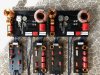
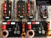
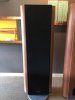
Here are the results... see pics
The cabinets were not sealed by anyone's measure- they (did) leak everywhere; not just around the drivers

They sound like....WOW!.... Blows the originals away

IMHEO- In my humble ears only - The bottom end always felt muddled/strained to me and the mid and highs now stage soooo much better (more open and upfront) while no longer fatiguing over time.

Now going to start on my next speaker project...
 

Attachments

  • Kappa ( Crossovers.jpg
    Kappa ( Crossovers.jpg
    153.4 KB · Views: 252
  • Front- MAIN.jpg
    Front- MAIN.jpg
    55.6 KB · Views: 248
  • New-Cross.jpg
    New-Cross.jpg
    146.7 KB · Views: 234
  • Cabiner Top.jpg
    Cabiner Top.jpg
    54.4 KB · Views: 215
  • Top Drivers.jpg
    Top Drivers.jpg
    51.8 KB · Views: 227
  • New Veneer.jpg
    New Veneer.jpg
    69.1 KB · Views: 227
  • Back.jpg
    Back.jpg
    65.3 KB · Views: 224
  • IMG_1696.jpg
    IMG_1696.jpg
    68.3 KB · Views: 224
  • IMG_1764.jpg
    IMG_1764.jpg
    38.3 KB · Views: 218
Last edited by a moderator:
Yes- Millersound on the Poly-domes (Bill is awesome).
I just got a set of Kappa 8's, so going to try the McGuire's on the Poly's and see how it goes.
 
Wow, truly beautiful set of speakers.
PS, I'm the lucky owner of Ren 90's $50.00 and CS 3007's $60.00
 
So I was curious as to the design of the crossover for the woofers for the Kappa 9's, and it turns out that the Infinity designers were pretty ingenious. The attached impedance graph is very similar to the K9 Extended ON graph with differences being explained by the variability of the woofer impedance with frequency and not a fixed 16 ohms.

What is ingenious about the response is that it peaks at about 29 Hz and falls off at about 12 db/octave which is the same as a sealed enclosure would have a roll off of for woofers below the F3 point. So the infinity people were trying to create a flat response from the F3 point down to 29 Hz by compensating for the roll of with the tuning circuit out front. The roll off from 80hz on is about 4dB/octave.

The only drawback to this approach is of course the low impedance point. But is does take a significant amount of more power to produce the same volume of 30 Hz vs 60 Hz in the sealed enclosure. As noted before some of the components are not optimal but this was a commercial product.
 

Attachments

Here are the results... see pics
The cabinets were not sealed by anyone's measure- they (did) leak everywhere; not just around the drivers

They sound like....WOW!.... Blows the originals away

IMHEO- In my humble ears only - The bottom end always felt muddled/strained to me and the mid and highs now stage soooo much better (more open and upfront) while no longer fatiguing over time.

Now going to start on my nex project

I seen these for sale for 6k.... hard pass on that
You did a great job tho
 
Last edited:
Couldn't you power the woofers with a separate amplifier, maybe one that has a built in low-pass filter for subwoofer use? This would make them sort of a cross between active and bi-amped. You could pick a "bass" amplifier that likes low impedance loads.

As for rebuilding the crossovers, it's not an impossible task, just one that takes time, planning, and probably few different attempts as well. Do you have a schematic of the crossovers you could post on here? I don't know if this will help, but I did this on a pair of AR9LSi, you can see the pictures in this thread :

https://audiokarma.org/forums/index.php?threads/acoustic-research-ar9lsi-restoration.528158/

Lee.
 
He redid the whole thing....not sure I would’ve done it that way....I agree that the iron core coils suck and should be upgraded...I agree on putting better than stock caps in but I like sticking to the original schem...just use better products...
 
Back
Top Bottom