• The move to the new server is done. There are some software and database maintenance updates in process. This has us passing the hat around to help out. We appreciate any donations. Seriously, even a dollar helps. The payment page may be found here - https://www.audiokarma.org/support.html

Inrush current limiters, my thoughts and yours.

There has been an excellent discussion so far of fuses and NTCs and yet there is another issue that is not addressed in this thread and that is construction technique. I bring this up not to embarrass anyone but because I have seen many photos on AK of "restoration" work that makes me cringe when I see it. In particular I see an almost complete lack of the use of any kind of insulation on the leads of resistors and capacitors. I refer to what used to be termed "spaghetti tubing" but is more likely today to be heat shrink tubing or Teflon tubing.

When any two leads cross there should be some sort of insulation between the two wires. It doesn't matter if they aren't touching when the unit is built, what's important is that there is no possibility that the two leads could short together. Over and over I see resistors and capacitors connected to tube sockets that cross one another with no insulation. They should absolutely be insulated.

Again, I am not saying that this is the actual issue the OP has experienced, I am stating that I see way too much construction that is exhibited on AK that is bound to fail eventually. So rather than point to some of these poor construction techniques and embarrass the poster, I am going to show my own mistake. Notice the photo below has pretty good technique for a unit that has been rebuilt and modified several times. My experience is that the first time a unit is built, it is painstakingly constructed, but as it is modified or used as a "breadboard" for experiments, the carefully crafted construction becomes much less organized and safe.

So below is an amp that was modified by me several times to dial in the circuit. Notice that in general the construction is descent, with several different types of tubing used that attest to its several modifications. But in particular I draw your attention to the MIT cap second from the right. There is no doubt is carries high voltage as it appears to connect the plate of one tube to the next tube's grid. Looking closely one can see the lead to the tube socket is not insulated, but far more disturbing is the screw holding the socket to the chassis is pointing up directly beneath the cap lead. OK, it doesn't touch now, but what if the unit is shipped, or placed down on a table hard, or any number of external forces that could move the cap towards the screw. Maybe that will never happen, but that's irrelevant, what's important is to always expect the worst to happen and build accordingly. Insulate those leads!


L1001486a.jpg
 
I've heard of houses catching fire --- with the circuit breakers intact. A lot of current in the wrong place (like next to something very flammable) to going to beat a fuse or circuit breaker.

As a general note, fire inspectors, particularly the municipal/state employees, are not always the most qualified nor insightful in performing their assignments. As in almost every other endeavor, the really good ones don't work for the government, but are in private/commercial industry.

Inspectors will look for obvious causes and ignition sources. Too often, when nothing obvious is discovered the cause is recorded as "electrical fire" and the case is closed. I personally had a liability case where the improper installation of a triple-wall chimney allowed the re-introduction of fireplace embers to be drawn into a chimney chase and kindled a house fire. The state inspector(s) couldn't fathom that, but the professional insurance inspector determined and proved the true reason. The state fire inspector saw melted Romex in the wall where the fire was kindled and immediately claimed "electrical failure" as the cause. Well, DU-UH! If a wall is ablaze, what would you expect the plastic insulated wire to look like? The insurance inspector had to testify and explain it to the inspector and the court, using photos of the damaged area to prove what actually happened. Getting the state inspector to acknowledge the error was like a comedic episode. The contractor's professional liability insurance paid the damage claim, and not the homeowner's insurance carrier.

In short (pun not intended), don't take the "official" government word as gospel. They're batting average might be 0.250 on a good week.

That said, breakers' trip curves really need to be understood before applying them to any protection role, but even the lightest gauge wire will pass an amazing amount of current before becoming hot enough to kindle a fire. The NEC ampacity tables for "open air" conductors should provide a clue for just what that current limit is.
 
... When any two leads cross there should be some sort of insulation between the two wires. It doesn't matter if they aren't touching when the unit is built, what's important is that there is no possibility that the two leads could short together.

If you ever worked inside a substation or even secondary switchgear, you might soil your garments. Bare copper bars are all over the place, and intentionally cross paths to reduce induction and EMI. They are usually pretty low voltage, however, rarely exceeding 345kV.
 
As I watched my fisher tube amp short out, zap like a welder for a full second and literally catch fire for a short time the other day due to a stray wire shorting B+ to ground the fuse did eventually blow but it got me thinking. I think a fast blow fuse is the better option for basically anything.

Can someone recommend a general inrush limiting setup for a tube amp? Maybe a thermistor part number or specification. Should it got directly to the B+ line or the 110v input? Would a delay start be better? The amp in question is an x-202-b using 7591 tubes.
1703535736630.png
Look up inrush limiter at a website for any major electronic parts supplier and you will see these thermistors that come in different ratings. Find out the current consumption of your equipment to select the right size. I use the CL-60 size in my mono-block tube amplifiers. Connect it in series with the hot lead of the AC power (NOT the neutral lead) and the matching AC input connection on your equipment. The device starts out cold with a DCR of maybe 15 ohms or so (lower for larger sizes) and as it heats up, the R drops to well less than an ohm. Mount the device away from any metal surface or device that does not like heat. The thermistor must stay warm in order to keep a low resistance when the equipment is in use. Of course, if you turn off the equipment (an amp, say) you need to wait for the thermistor to cool down before powering the amp up again. If the thermistor does not get a chance to cool down before you power up again, you will get little or no inrush surge reduction. In my amplifiers, I added a relay with a time delay, and a low-ohms power resistor does the current limiting. The relay shorts the resistor out after a few seconds. The danger of this approach is that if the relay fails to close, the resistor will get hot enough to maybe cause a fire.
 
Last edited:
Have been in plenty of old gear with no or very limited amounts of sleeves. Its not a bad idea and i use it in places but not on every single lead. Anywhere things cross gets a sleeve though
 
My wife and I own a campground and you would be amazed at the abuse a 30 (single-pole) or 50 amp (double-pole) can take before it trips. I have seen plug blades melt away where the copper blade goes into the molded plug. This is usually where the problem emanates from then the receptacle on my power pedestal gets damage from the heat and excessive current. If the right conditions are sustained, the circuit breaker may trip... it may not and continue to heat-up (enough to not trip) and then the breaker fails. This condition over many cycles will weaken the breaker and the breaker will then completely fail too.

A circuit breaker is there to technically protect the wire feeding the circuit (upstream), not equipment connected to it.


Totally off-topic, but I'm enamored of the fact that you own a campground. ;-) If you weren't 3K miles away I'd stay there. ;-)
 
Have been in plenty of old gear with no or very limited amounts of sleeves. Its not a bad idea and i use it in places but not on every single lead. Anywhere things cross gets a sleeve though
That's why it's a good idea to go through these vintage units. Especially, the small, cheap table-top radios. Kinda common for failures and other issues being due to poor wiring routing and insulation (old cloth cover wearing out).
 
In my amplifiers, I added a relay with a time delay, and a low-ohms power resistor does the current limiting. The relay shorts the resistor out after a few seconds. The danger of this approach is that if the relay fails to close, the resistor will get hot enough to maybe cause a fire.
This approach can be implemented without an actual time delay if the resistor is a fairly large value. The drop across the resistor while the PS capacitors are charging will prevent the relay from closing. This also prevents the current surge that normally takes place due to the cold resistance of the tube filaments. A double-pole relay with appropriate arc suppression should last for many years in this application, and a wirewound resistor won't catch fire if the relay fails.

Jack
 
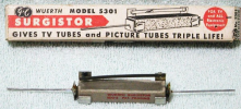
"back in the day" there was an even lower tech solution for this. The heat from the resistor would close the bi-metal contact and current flow through the contacts kept it shut to bypass the resistor. Somehow I can't help but wonder about the long term reliability of this thing, and of course all the exposed mains voltage.


1703606435448.png
 
"Back in the day" could cover so many topics of questionable items used for many different purposes...

Who could of thought talcum powder could have been a bad thing? And the list is endless so many years later.
 
index.php

"back in the day" there was an even lower tech solution for this. The heat from the resistor would close the bi-metal contact and current flow through the contacts kept it shut to bypass the resistor. Somehow I can't help but wonder about the long term reliability of this thing, and of course all the exposed mains voltage.


View attachment 3071565
Never saw one of these. Guess that means the device didn't become standard practice.

I find that over-wattage resistors (I like wire-wound or metal-oxide ones) in the power supply filter chain helps to absorb some of the excess early in-rush.

! doghouse -- new (SMALL).jpg
 
Last edited:
"back in the day" there was an even lower tech solution for this. The heat from the resistor would close the bi-metal contact and current flow through the contacts kept it shut to bypass the resistor. Somehow I can't help but wonder about the long term reliability of this thing, and of course all the exposed mains voltage.


View attachment 3071565
Question is, once the resistor is shorted and cools off, does the contact open again, starting a never-ending repeated open-close sequence?
 
My understanding is that the metal piece stays warm enough because of current flow through it to keep the contact closed. It only opens again once power is cut and it completely cools. Would be pretty useless to have it just open and close constantly.
 
yep. Makes me wonder about the long-term durability. A modern thermistor with no moving parts seems like a better solution now, or if space isn't at a premium, a resistor with a bypass relay on some sort of timing circuit.

This also all depends on the idle current draw, tube stuff has a fair bit of it and the current swing from idle to full output isn't huge. If we're talking solid state amps, most of them idle at very little current and have a significant swing from 0 to 11. Can't use a thermistor in those very effectively because its not liable to get hot enough to drop the resistance down.
 
"back in the day" there was an even lower tech solution for this. The heat from the resistor would close the bi-metal contact and current flow through the contacts kept it shut to bypass the resistor. Somehow I can't help but wonder about the long term reliability of this thing, and of course all the exposed mains voltage.


View attachment 3071565
At some point you would think over time the contact would get pitted, and even weld itself to the metal strip. I wouldn't trust it with a 10' uninsolated wire. :biggrin:
 
NTC's on solid state Class A amps like my DIY Krell KSA-50 clones work great, especially having a giant toroid and huge reservoir capacitance.
 
At some point you would think over time the contact would get pitted, and even weld itself to the metal strip.
particularly with what I expect is a fairly slow close time. Too much time with a gap between those points where it can arc.


NTC's on solid state Class A amps like my DIY Krell KSA-50 clones work great, especially having a giant toroid and huge reservoir capacitance.
my Phase Linear is pretty much the opposite case. Idles at maybe a half amp, but at full output its pulling around 8 amps.
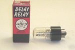
 
particularly with what I expect is a fairly slow close time. Too much time with a gap between those points where it can arc.


my Phase Linear is pretty much the opposite case. Idles at maybe a half amp, but at full output its pulling around 8 amps.
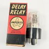
Yep. I have about 13 PL amps including one D500, which needs some serious TLC. I want to design a new PCB for it since the original is almost unusable. Even though it will be a one off PCB, it is worth it to me since it is such a beast of an amp. I'm also going to convert it to full comp too.
 
Back
Top Bottom