• The move to the new server is done. There are some software and database maintenance updates in process. This has us passing the hat around to help out. We appreciate any donations. Seriously, even a dollar helps. The payment page may be found here - https://www.audiokarma.org/support.html

Is There A Thread/Schematic for Putting EFB Into A Scott 7591 Based Unit?

1rebmem

Halffast
Subscriber
I'm interested in putting Dave G's trade marked EFB circuit in my Scott LK-72.
It matches this LK-72B schematic: http://hhscott.com/pdf/fs/LK72B.JPG
Ideally EFB with screen grid control. I wonder if my B+ would rise too much due to reduced current loading on the main B+ supply resistor string and require thus reduction.

Has anyone done EFB on a Scott 299 with the 7591 outputs?
I've installed EFB on a Fisher using this schematic: http://akdatabase.com/AKview/albums/userpics/10007/Fisher 500c EFB mod13.pdf
Perhaps it's a good foundation to adapt to the Scott?
 
Last edited:
Register to hide this ad
This is as close as I've seen for a Scott unit:

https://audiokarma.org/forums/index.php?threads/efb-circuit-in-hh-scott-lk-48.717689/

I'm restoring a Scott 272 and have just added EFB to it and am doing some optimization now, but it's an EL34/6CA7 amplifier with some differences compared to the above and no screen grid control needed. I have an LK-72 but it is stock (so far!).

The circuits are basically the same; variations on Dave's circuit adapted to the particular amplifier.

Dave
 
The Fisher 500C EFB mod seems to be a good start for what you are looking to do. A cursory glance at the 500C schematic including the EFB circuit used there vs. the stock LK-72B schematic says you can very likely use the exact same EFB circuit topology, you would just need to tweak some resistor values.
 
Last edited:
Thanks Dave and kward.
I think Dave your 272 is different enough to not really help me since your plate and screen are essentially at the same potential. But you knew that?

My B+ is 32v higher than the 500C example, does that require gate resistor changes? If so I'm lost......
I assume I want the same plate to screen voltage delta as the 500C example correct?
As to the bias supply, I have bias and balance pots for each channel so I'm guessing my best approach would be to replace all four of my pots with 10K's and rewire to Dave G's IBBA:
Screen Shot 2019-08-03 at 6.05.49 PM.png

I probably have all the parts to build it now, just not sure on resistor changes so, kward...........wink wink.:naughty:
Tks. Jef
 
Last edited:
This thread addresses EFB with the 7591 (only beginning/end quoted):
https://audiokarma.org/forums/index...r-800-500-early-version-400-receivers.539265/

With the X-1000 project showing light at the end of the tunnel now, I thought I would take a moment to update the results of my work regarding EFB(tm) operation, and the 7591 family of output stages as typically used in these and about a bazillion other Fisher, Eico, Scott, and other manufacturer's amplifiers/receivers. To be clear, these can be identified by units that include ALL of the following:

1. They employ some version of the 7591 class of power tubes, which includes 7868 and 6GM5 tubes.

2. They employ true fixed bias operation. For the moment then, that eliminates those units that power some portion of the small signal tubes by way of the output stage cathode current. These designs are correctly identified as cathode biased designs, often disguised as a fixed bias amplifier because they contain a bias control. However, they truly are a cathode bias design, with the traditional cathode resistor element simply being replaced by the resistive elements of the heaters in some of the small signal tubes. In those cases, output stage current draw cannot be reduced, or the heaters will not light. At the very least then, installing EFB in those types of units will first require an alternate source of heater power to be developed to light those tubes, and then, an output stage from one of those units would then need to be modeled to determine the best EFB operating point for the revised operating conditions.

3. They are rated at -- and can deliver ~ 32 to 35 watts RMS per channel. Relative to EFB, this point is what distinguishes early versions versus the later version 400 receivers, where it is a fact that the later version units cannot develop this power output level. For the purpose of this point then, it is ASSUMED that Fisher did not play the game of musical output transformer chairs in their 500 and 800 series of receivers, and that they can all in fact deliver the power range noted above through out their serial number production runs. Physical style of the OPT is unimportant. The fact that it is about a 6500 ohm unit, is. Any info that anyone has regarding this point relative to the 500/800 series of receivers would be appreciated.


...

As you can see then, EFB does offer advantages to this type of operation with 7591 class tubes as well, which can be tailored to your specific needs as appropriate. When the X-1000 project comes to an end, I will be working with some of BuzzK's projects to develop these concepts in more detail. However, this overview will at least serve to detail what those possibilities include.
​

Dave (@dcgillespie) might be able to point you at a more definitive reference.
 
For starters I’d keep the screen voltage the same as it is in the stock circuit but put it under EFB control. You need a gate voltage divider that will deliver the desired screen voltage + about 4 volts. (Enhancement mode mosfets run the output at about 4 volts less than the gate at the screen currents we’re talking about here.)

I think the grid control circuit will be very similar to dave451’s component values since the voltages needed are nearly identical. I think he is going to publish it after he does some more testing.

I can draw something up but I won't be able to get to it for a few days. If you can wait that long I'll look at it then. If someone else gets to it sooner that's great.
 
Last edited:
I can draw something up but I won't be able to get to it for a few days. If you can wait that long I'll look at it then. If someone else gets to it sooner that's great.
That would be great, thanks.
I'm not able to figure it out.
And if you have the time to type out your process, to educate me/us, even better.
Jef
 
You are correct; the 272 does not require screen regulation with the screen voltages so close to the plate voltage. The EFB adaption for it only deals with fixed bias voltage control. Kward provided the circuit adaptation for the 272 based on Dave G's work. I'll be posting it next day or so 'as installed.'
 
I’ve been working with Dave451 on a private thread to work through the design of adding EFB to his 272. I think we have the final changes in place now but since I don’t have a 272 myself, Dave and his amp are the test bed. Once he reports back that things are working, I can adapt that design to this amp.

===

And I keep forgetting to add that EFB is a Dave Gillespie trademark.
 
Last edited:
Once he reports back that things are working, I can adapt that design to this amp.
I really do appreciate your time on this!

Once EFB (tm) is installed in a given amp, how are the new and lower quiescent idle currents determined?
Jef
 
With a distortion or spectrum analyzer. Or you make an educated guess given another EFB installation on a similar amp where someone has done that distortion or spectrum analysis. The idea being that with EFB, there is an optimal bias setting that minimizes distortion at max output power. Unlike without EFB where there is no distortion null; distortion just inches slightly down the hotter you bias the output stage.
 
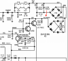
To start working on this there are three things I need to know: (see the red arrows in the schematic below)

1. The DC voltage at the negative junction of the bridge rectifier on the bias winding
2. The AC voltage between the two leads of the bias winding
3. Your line voltage.

upload_2019-8-10_22-44-57.png
 
1. The DC voltage at the negative junction of the bridge rectifier on the bias winding
2. The AC voltage between the two leads of the bias winding
3. Your line voltage.

I have:
-58.6vdc leaving the bridge.
54.75vac feeding the bridge.
119.6vac line (122 before CL-80)
Jef
 
Looking more at this, it seems to me the Fisher 500C EFB(tm) schematic would work fine, I believe.......
http://akdatabase.com/AKview/albums/userpics/10007/Fisher 500c EFB mod13.pdf
My LK-72 B+ runs almost 30 volts higher but wouldn't the 500C EFB(tm) keep the voltage relationships correct?

For bias supply I wouldn't need the voltage doubler ckt because my LK-72 already has -56v out of the heater/bias bridge:

Screen Shot 2019-08-11 at 2.02.12 PM.png

I think I could run my -56v to Q101 collector just like here on the 500C EFB(tm) schematic:
Screen Shot 2019-08-11 at 2.01.40 PM.png

Again, here is my schematic, and my voltages match pretty close:
http://akdatabase.com/AKview/albums/userpics/10007/HH Scott LK-72B Schematic D-LK72B-C1 Sub 0.pdf

Am I thinking right?
Jef
 
Last edited:
I like the idea of using Dave G's IBBA ckt, being a fail safe design. I posted a screen shot of it up in post #4.
My LK-72 already has 2 bias and 2 balance pot's. I'd simply replace them with 10K pot's and wire to Dave's design.

Thoughts?????

Jef
 
The voltages on the 500C example you referenced in post #18 are close but not exact for what will work optimally for the LK72. I'm approximately half way through the design for the changes you'll need for the LK72. If you want to plow ahead you can try to adapt the circuits as you've discussed. If you want to wait, I will finish the design and post it, then you can decide if you want to use it or not.

There are several important considerations, which I am accounting for in the design I will post, which you should consider if you adapt the 500C example:
  1. Offer the same bias and balance swings as exists on the stock LK72, which are: -17V to -24V bias swing, and 3V side to side (-19V to -22V) balance swing.
  2. Offer a "master bias" control on the EFB board, so that you can adjust the bias voltage fed to the bias/balance circuit up or down a bit to accommodate a large variation in tube characteristics, but without needing to design a large swing into the bias/balance circuits themselves. Matched tubes are still recommended, but if you want to run worn out tubes that bias cold, or new tubes that bias hot, you might run out of bias pot rotation, either clockwise or counter clockwise. In this case you can slide the master bias control on the EFB board up or down to position the master bias voltage so that you have usable bias pot rotation regardless of tube characteristics. This is the same type of solution provided for the Scott 272, and it works very well, not to mention provides ultimate flexibility, all without needing to design into the bias/balance circuit itself overly large voltage swing capability.
  3. Use the stock bias/balance pots so that you don't need to swap them out. Unless you WANT to swap them out, then the design can fairly easily accommodate lower resistance bias/bal pots. In either case though, it is important to offer the same bias/balance swings as provided on the stock amp.
  4. The bias voltage provided on the LK72, when both bias and balance pots are centered is -20.3V. Therefore yes, it will be possible to adapt EFB to your amp without needing a voltage doubler rectification circuit. (NOTE this was not the case on the Scott 272 because the bias voltage at center was significantly larger at -45V, but with essentially the same AC secondary bias winding voltage as is used on the LK72).
As a note, the bias/balance control circuit I'm disusing here offers a method to DC bias and balance the pair of output tubes together with two separate controls. This is not an "individual bias balance adjust modification" (aka IBBAM). Rather the bias and balance circuits work in tandem on the pair of tubes together, but still offer the flexibility of an IBBAM. This works by first adjusting balance between the two tubes with one pot adjustment, then after balance is set, slide bias up or down for both tubes simultaneously with another pot adjustment, all without destroying balance. Four pots total are used (a bias and balance pot per pair of tubes), but the approach is better (my opinion) over an IBBAM solution because you don't need to fiddle with balance when adjusting bias as you would with an IBBAM.

So let me know how you want to proceed. In summary:
  1. Do you want to see the design I come up with for the LK72?
  2. Do you want to use the stock bias/balance pots in the new design?
 
Last edited:
Do you want to see the design I come up with for the LK72?
Yes sir, sounds great!
Carry on please.
I will await your design. I like your idea of the master bias.

I was just trying to gain some understanding on my own. I did not think I could just slap in the 500C ckt, well it may have worked but certainly would not have optimized to gain all the benefits of EFB.

Thanks,
Jef
 
Back
Top Bottom