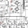
Here is the design. Because I don't have an LK-72 on which to test this circuit, I will call this entire thing "draft" until you build and test it. Both the EFB circuit and the bias/balance circuit must be used as a matched set. Don't try to implement one without the other. It won't work. You must implement both circuits for the amp to function properly.
First the EFB circuit.

You'll see that this is very similar to Dave G's work on the Fisher 500C, with subtle differences to account for the slightly different voltages used. The trickiest part is the resistor labeled R (shown as 2.4K in the above schematic). You should adjust the size of that resistor until you measure -50V at the junction labeled "-50V". You might need to adjust that resistor up or down in size. I took my best educated guess at what I think is the right size. If you need to error, error on the side of putting a lower voltage (meaning more negative) at that -50V junction.
The master bias adjustment is the 10K pot shown in the schematic. Adjust it until you read -30V on the output. If you want to hard wire -30V output, you can replace that 10K pot with a resistance of (approximately) 4.1K. It's nice to have a master bias adjustment though, so that you can tweak the output bias voltage by a volt or two in either direction to account for hot or cold biasing of tubes, without running out of bias pot rotation in the bias/balance circuit, below. I usually use a small PCB mount trimpot in this position, that I mount right on the same perforation board as the EFB circuit is built on.
Next, the bias/balance circuit:

This circuit uses the stock bias/balance pots and offers essentially the same bias and balance swings as the stock circuit. It's also a simpler circuit than the stock circuit. It has a fail-safe mechanism built in that the stock circuit does not, which is if the bias or balance pots ever break, or stop working because of dust or dirt or whatever, the bias voltage will go more negative, sending the output tubes into cutoff or at least run them cooler. In the stock circuit, if the bias or balance pots break, the bias voltage becomes undefined, which is a sure recipe for output tube red plating.
As for the "optimal" quiescent current setting that will minimize distortion at full power output. That setting is probably somewhere in the vicinity of the same value Dave G. found for the Fisher 500C. But I expect it will be a little higher (maybe 10% to 15%) since the screen voltage used on the LK-72 is higher than on the Fisher 500C. That's a guess. The optimal bias setting will need to be determined empirically. I know of no other way to find the optimum setting except through using a spectrum analyzer or THD distortion analyzer.
===
Note neither of these schematics are my design. I adapted them both from Dave G's work. You mentioned you were interested in knowing how to design this, so that you could perhaps do it yourself in the future on an arbitrary PP amp. It's more words than will fit in this post, and each installation is unique. But if you really want to know, I can show you the basic steps.
Good luck! Let me know if you have any questions.
First the EFB circuit.
You'll see that this is very similar to Dave G's work on the Fisher 500C, with subtle differences to account for the slightly different voltages used. The trickiest part is the resistor labeled R (shown as 2.4K in the above schematic). You should adjust the size of that resistor until you measure -50V at the junction labeled "-50V". You might need to adjust that resistor up or down in size. I took my best educated guess at what I think is the right size. If you need to error, error on the side of putting a lower voltage (meaning more negative) at that -50V junction.
The master bias adjustment is the 10K pot shown in the schematic. Adjust it until you read -30V on the output. If you want to hard wire -30V output, you can replace that 10K pot with a resistance of (approximately) 4.1K. It's nice to have a master bias adjustment though, so that you can tweak the output bias voltage by a volt or two in either direction to account for hot or cold biasing of tubes, without running out of bias pot rotation in the bias/balance circuit, below. I usually use a small PCB mount trimpot in this position, that I mount right on the same perforation board as the EFB circuit is built on.
Next, the bias/balance circuit:
This circuit uses the stock bias/balance pots and offers essentially the same bias and balance swings as the stock circuit. It's also a simpler circuit than the stock circuit. It has a fail-safe mechanism built in that the stock circuit does not, which is if the bias or balance pots ever break, or stop working because of dust or dirt or whatever, the bias voltage will go more negative, sending the output tubes into cutoff or at least run them cooler. In the stock circuit, if the bias or balance pots break, the bias voltage becomes undefined, which is a sure recipe for output tube red plating.
As for the "optimal" quiescent current setting that will minimize distortion at full power output. That setting is probably somewhere in the vicinity of the same value Dave G. found for the Fisher 500C. But I expect it will be a little higher (maybe 10% to 15%) since the screen voltage used on the LK-72 is higher than on the Fisher 500C. That's a guess. The optimal bias setting will need to be determined empirically. I know of no other way to find the optimum setting except through using a spectrum analyzer or THD distortion analyzer.
===
Note neither of these schematics are my design. I adapted them both from Dave G's work. You mentioned you were interested in knowing how to design this, so that you could perhaps do it yourself in the future on an arbitrary PP amp. It's more words than will fit in this post, and each installation is unique. But if you really want to know, I can show you the basic steps.
Good luck! Let me know if you have any questions.
Last edited: