• The move to the new server is done. There are some software and database maintenance updates in process. This has us passing the hat around to help out. We appreciate any donations. Seriously, even a dollar helps. The payment page may be found here - https://www.audiokarma.org/support.html

Is this motorboating and how do I control it

audiodon

Addicted Member
Hi,
I'm in the final throes of finishing the restoration of my beloved early style Fisher X-1000.

I'd wanted to put it in my office system again. It looks ready.
While this is a Fisher issue, I'd like to ask the help of the larger tube community.
I had some weak output tubes and was doing some tube substitutions and might have short-cycled the unit while swapping tubes around. It is a solid-state rectified unit and I don't know that doing that created my problem.
Symptoms:
Now, with good strong tubes all around, and with all voltages within 5% of what they should be, when I turn it up on the variac and get near or over 400 volts on B+ (should be 412), sometimes I get an oscillation in the power supply that stops me from reading the DC values of the power supply caps and pulls the woofers in and out at what I think is some division of 60 cycles, like maybe 7.5 cps, not sure on that frequency though.

What I've tried:
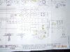
1. I thought it might be the first can cap, which gets warm. These all were changed and all have 1989 stamps on them, making them 23 years since date of manufacture. So, I replaced the first one, which according to the schematic is
C57B@60uf525V and C57A@30uf@525V. I also modified the values of R111 and R104 from 750 ohms to 660 ohms @ 5 watts. I wanted the value one step down from B+ to be a little closer to the B+ value for the EL-34 output tubes.
No change.
2. The diode bridge terminating at CR4 and CR6 has wondercaps across the diodes. Pulled them. No change.
3. When it does go into this pulsing or oscillation mode, if I pull the variac down to about 110 volts, it goes away and I see a steady DC voltage again.

When not pulsing, oscillating, motorboating, whatever, All voltages are within 5% of where they should be. Most are within about 1%.
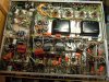
I've included a photo of underneath the chassis. As you can see, the restoration has been quite extensive.
The tubes are strong and hold bias and are AC and DC balanced to spec.

A few final points.
1. I see that there's no schematic for this in digital docs. I'll have to remedy that, but it'll have to wait.
2. I don't want to grasp at straws anymore. There's got to be a method to get to this.
3. Negative bias is rock steady as are filament voltages.
4. I'm not getting a good solid AC reading across the middle of the power supply diode bridge. It goes to the red and red/yellow leads of the power supply. I can get measureable AC and DC, which I find confusing.
5. One more thing, the two death caps, C68 and C69 are original. They're really tucked away in there and are hard to access. Also, i have CL-80 thermisters on each black lead of the power supply to pull the voltage down a bit at the power tranny.

attachment.php
 

Attachments

  • x1000inlab.jpg
    x1000inlab.jpg
    66.6 KB · Views: 78
  • underchassisfull.jpg
    underchassisfull.jpg
    134.1 KB · Views: 88
  • psschematic.jpg
    psschematic.jpg
    77.8 KB · Views: 415
Last edited:
Register to hide this ad
if you have an esr meter check the other power supply caps,I had a Scott amp that had a bad power supply cap that would motorboat at line voltage,but when lowered it otherwise worked well,if you don't have an esr meter,or cap tester,you can measure the ac voltage across the caps to check them
 
Don -- Does it do this in both channels? Does the volume control or bass control affect the intensity or rate of oscillation?

Pull out the driver tubes to the output stages and see if the problem doesn't go away. If it does, the problem could more likely be a power supply cap feeding the driver stages.

Dave
 
I would like to add:
1. This happens at more like 1 or 2hz than 7.5 hz.
2. It happens on both channels.
3. The coupling caps are the stock value in all positions.

I was suspecting the diode bridge or transformer but have been thinking power supply too because the coupling caps later down for the lower voltages remain stable and display voltage, even when the unit is motorboating.

I'll get to the next step of trying pulling the drivers and report back as soon as everyone's awake in the house.

If measuring the AC voltage across the power supply caps, what should I look for?
 
Don -- one more thing to consider that can relate to problems like this: Since the problem happens in both channels, it is natural to assume a power supply problem because it is the only thing common to both channels. However, based on the recent problems I was chasing down with my SA-100 project, don't discount grounding problems, either. That "system" is also common to both channels, and can cause all manner of weird problems depending on where the compromise exists in the circuit, and the extent to which the compromise exists as well.

Dave
 
I know a few more things now.
1. Pulling the 12AU7 phase inverter makes no difference.
2. Pulling the EF-86 driver tubes (two, one for each channel) makes no difference.
3. Pulling the upstream 7247s makes no difference - well, read the observation at the bottom. Minor difference.
4. This had been wired with a three wire plug. I'd tried using a cheater plug last night and it made no difference. Today I snipped the green leg that's soldered to the C57 can cap lug and it made no difference.
5. I put in my test quad of Sovtek EL-34s and that did stop the motorboating. It also pulled down B+ to under 325VDC, which is why it stopped the motorboating. As the voltage began to rise, the motorboating started again.
6. I've done all this recent testing with 8 ohm load resistors across the outputs and with the volume all the way down. It happens in both output channels.
7. I tried a few grounding tricks with alligator clips and that makes no difference, but it may not be ground enough.

As an observation, pulling the second 7247 did seem to change the period of the motorboating frequency by halfing it, but that was not reproducible when I tried it a second time.

No ESR meter, but I do have a Heathkit cap bridge with a tuning eye, as well as a handy dandy digital cap value checker.

I'm still leaning towards replacing all the power supply can caps.
 
Last edited:
My go to textbook (by HJF Crabbe) suggests that LF instability or motorboating is caused by a high impedance or inadequate decoupling in the HT system. The fix is to 'ensure that no two stages share a common HT resistor, unless a sufficiently large decoupling cap is connected to the common point.'

Otherwise it caused by a negative feedback fault. That can be checked by disconnecting the NFB. If disconnecting solves it, raise the value of grid caps to 0.1, 0.25, or even 0.5uf.

Do either of these lines look work investigating?
 
I put 20uf caps where it called for 200uf caps in my Sansui 1000A and got some pretty bad motor boating. So low can do it too.
 
I would start with the can caps myself. They should not get warm beyond slightly above room temp.

Use the heath cap/resistor bridge to see what it shows, but I suspect there is one leaky section. ESR is not a major factor in conventional supplies, so for testing, you can use the smaller electrolytics with correct voltage and capacitance.

There are 2 caps in the middle of the image that "might" contribute to the problem since they have a metal jacket, are they resting against anything?

The grounds were mentioned, I would not rule out the potential for that being the case with a cold solder joint.

Additionally, check to make sure R131 and R132 are not open or sufficiently altered from their orignial values. as well as R105,112,113,129 and R130. It would not hurt to clean up the rias adjustment pots as well. And also check CR3 to make sure it has at least a 10:1 ratio. Which would also be a good idea to check CR1 and CR2 as well.

You might also compare yours to a "101 A" or "101 B" as I encountered the same issue while truouble shooting a similar unit with 6BQ5 finals and had 2 stencils in different places- "!01 C" and "X-1000" also. Topology is essentially the same, mine has a bad output transformer.
 
I did a quick google image search for "motorboating" about six hours ago. Ummm..... What were we talking about again? :D
 
Don -- Pulling the driver tubes completely eliminates any NFB stability related issues. That means that the oscillation is directly related to the output stage and/or the power supply for it, so this certainly is a strange one.

Personally, I would go after the bias supply next to make sure it is not injecting some LF undulations from a cap trying to fail in that circuit.

Another thing you can try is grounding the grids of each output tube through a .25 uF cap of at least 100 volt rating. If you ground the grids of both tubes within one channel (one cap per tube) and that channel still oscillates, then the problem must be B+ related since the grids will effectively be grounded with respect to an AC influence during this test.

Keep us posted!

Dave
 
Hi Don- I would also suggest getting rid of the two 600 ohm power resistors and go back to the stock values of 750 ohm/5w for both..or higher. Maybe even go to 1K if you have these just for troubleshooting. You might consider changing one out and compare the difference between the channels to see if you can see a change.

Have you checked the 4 diodes in the bridge? If the unit were mine I would upgrade them anyway.

I have the photofact for this unit if it will help. Can't help but notice how cramped the underside is now vs. the stock unit. Maybe you have a lead routing issue as well? Wouldn't expect that in a DC power supply but maybe there are some signal wires that aren't happy. A little prodding with a chopstick might be insightful.

Good luck!
 
Last edited:
I'm going to dig back into this now.
A couple things:
1. The bias supply is new, or newish.
2. This happened to an otherwise stable integrated amp where I was tube rolling 5751s in for 12AX7s in a preamp stage after finishing what I thought was everything it needed. By otherwise stable, I mean that I have not changed any components or resistors recently. I was simply getting ready to button it up and put it back in rotation after changing the bias supply and a few other oddball pieces. The amp is essentially fully restored, but the can caps are now 20+ years old.
When I got it, the power supply had been updated some years before, but I put in new resistors from the volume pot on out, all new coupling caps, not messing with the values, including the caps in that rotational switch assembly, and put in and biased up for a different quad of tubes. It had 100+ hours on it of occasional listening since I'd dug into it.
thedelihaus had finished a front panel restoration, and I was testing it out and getting it ready for use when this occurred.

This motorboating is a corner case problem on what I thought was a finished amp.
 
Let's go at this thing from another angle -- one of current draw. If you remove the output tubes from one channel, will the other channel still motorboat -- and will either channel do/not do it in this condition?

Dave
 
I spent a frustrating day thinking I was narrowing this down by process of elimination and I have not yet come up with the answer.
I'm going to reread the thread and see what suggestions I have not implemented.
Basically I've done the following:
1. Put a 60uf 500V cap in parallel with most power supply caps to test and see if a change would occur.
2. Replace the can cap that gets too warm when left on, C57A and C57B. Reinforced the grounding including using liquid rosin and resoldering the grounding points on the can cap.
3. Try four new diodes in the diode bridge. No difference. Also tried the diodes with no power supply caps connected. No difference. Still 325V max before motorboating when B_ should be 312Vdc.
4. Double-check the DC filament section with the two 1000 uf 35V caps, which is also new a hundred hours ago.
5. Trace out the wire colors on the power transformer so I know which wires go where.
6. Check the negative bias supply and found the voltage off. Bypassed the dropping resistors I'd put in there to get the negative bias values to what is suggested in the schematic. All those resistors are new and measure to 1% tolerance. Also, all three caps in the negative bias supply have also been replaced. By new, I mean I did them last Spring and have used the unit intermittently since then, putting 100 hours or so of use on it. Voltage is still fluky here and this section is still suspect.
7. Since i had an unusual negative bias supply voltage in #6, I swapped the power transformer, suspecting a short in the windings of the red wires that go in the center of the diode bridge or the negative bias supply with another one from a different X-1000 that I have in the vault for later restoration. I'm grasping at straws now, I guess.
8. Pulled both pairs of output tubes one pair at a time.
9. Pulled the red tap off both output transformers to see if B+ would stabilize.

No difference with any of these changes. Invested a good part of the day here, at least a good five-six hours.
What's next?

A. Considering changing the 30/30/30 (C56A-C) can cap. I have a replacement on hand also.
B. The last can cap is in a clamp. I'm considering unclamping it and reclamping it to check and verify the ground. That's the C38 cap. That one has been rock steady though, even when the rest of the power supply motorboats.
C. I may have to lift a leg on the resistors in the negative bias supply one more time to check and verify.

Someone suggested earlier that there were some coupling caps with metal covers. They're Russian K40Ys and are encased in clear shrink wrap.
 
Last edited:
I think next up is a recheck of the negative bias supply components. It's nagging the back of my mind.

I've been looking at the "motor boat" MC225 with similar nagging. I'm getting grid voltage that oscillates between -21V and -24V on all four tubes. In fact, I'm getting oscillation almost everywhere. I'm starting to suspect the multi-section caps which are near new CE and Authenticaps. Carry on, I feel your pain!
 
Back
Top Bottom