• The move to the new server is done. There are some software and database maintenance updates in process. This has us passing the hat around to help out. We appreciate any donations. Seriously, even a dollar helps. The payment page may be found here - https://www.audiokarma.org/support.html

Is your unobtainium power switch worth $5 and an hour or so of your time?

Trying to do this Triac soft start mod on my Onkyo TX 560, really need someone to help me to verify this for me, this is just my own working sketch based what I have on the unit and my understandings. Please understand I don’t have any electronics background, purely mu own “guess”.
Thanks a lot.
8DA822EE-9CFB-4E5B-8A68-0946AE55BD34.jpeg EE8811EA-7C49-4566-A308-636FB9FF257A.jpeg
 
A couple of points: this is not a soft start circuit. Its purpose is to substitute the triac for the original switch in switching the line current, thus taking the load off a delicate or failing (and hard to replace) original switch. Also, if you use a "snubberless" triac, you don't need the snubber (capacitor/resistor combo.)

I doctored your diagram to show the correct way to wire the triac (and removed the snubber, presuming you would be using one of the parts discussed in this thread that does not require one.)

Edit: Doctored diagram replaced w/ revised version, which corrects errors in the original diagram that merlynski pointed out (below.)

upload_2020-11-14_4-31-15.jpeg

Note that the original switch is taken completely out of the original circuit. It is only connected to the triac.
The hot side of the incoming power goes to M1. M2 goes to the transformer, plus there's a separate lead from M2 to one side of the original switch. A lead from G goes to the other side of the original switch.

One important note: this mod involves mains power. You could hurt or even kill yourself if you do something wrong, or could cause a fire. You said you have no electronics background and are guessing. Mains power is not something to guess with! Unless you are entirely comfortable with how this circuit works, and in working with mains power (as well as your ability to do the work properly) it may be best to have someone with more experience help you with or do the mod.
 
Last edited:
@EC1
@50 Green
I see a very dangerous situation in the drawings in the two previous posts, there is a direct connection between the primary side of the transformer and "ground":
danger_connection2.jpg

This may cause the chassis to be at the ac line voltage potential. upload_2020-11-13_9-20-3.gif
Also, the resistor that is shown in series with the transformer winding is incorrect. If that is the resistor shown in the SM as R901 3.3MΩ, it will block current through the primary, and the unit will never power up.
PLEASE discard that whole drawing as it is both dangerous and nonfunctional. I recommend deleting the drawing from the thread/posts entirely so no one mistakes it for a correct application of a triac installation.
Here is a copy of the AC primary side from the service manual:

AC_power.png

Here is how to correctly wire in the triac to your Onkyo:

AC_power_triac.png
 
@merlynski , do you mean these 2 red lines connecting to ground?
I just happen to put the ground in that particular spot. It does not mean connection.
6198657A-250F-4BAF-9CDB-F90BF55B98F6.jpeg
Sorry to create any trouble here and thanks for all your input and help.
 
@merlynski , do you mean these 2 red lines connecting to ground?
I just happen to put the ground in that particular spot. It does not mean connection.
View attachment 2033877
Sorry to create any trouble here and thanks for all your input and help.
@EC1
No, I am not referring to the red lines, I was referring to the blue line between the word 'GROUND' and connection dot on wire between the resistor and the BLK labeled transformer wire (outlined in turquoise rectangle, below). To me that clearly indicates a connection between that wire and 'ground', which is the chassis in most audio equipment, including your Onkyo (I checked the schematic).
Since you used similar labels on the wires "To switch" to mean a connection, I took the same meaning for the word GROUND.

danger_connection3.jpg

The red lines I understood not to be connected (to GROUND), by the color and the break across the word. Schematics have drawing conventions which are understood by those who know how to read them. You stated you had no experience with electronics, so, taking that into account, I knew you did not understand the the conventions, but I did not want anyone to use your drawing, thinking it was correct and safe. Like 50 Green said "Mains power is not something to guess with!"

The symbol in the green circle in the image below means it is a common chassis connection, often called 'ground'. The 3.3MΩ resistor will bleed off static charges but will not pass enough current to be hazardous, even if that wire were plugged into the HOT side of the outlet.

AC_power_chassis-common.png

In your drawing, when the amp is plugged in, if the triac turns on, the HOT side of the AC line could be connected to the chassis through the transformer primary. If a person was to touch the chassis and a real ground or a neutral connection, enough current could flow to cause a fatal shock. Connecting the amp to another unit through an audio cable could put that voltage onto another unit's chassis or ground and damage the equipment.

Please understand this is not a personal attack at all, but I saw a potential lethal wiring mistake and could not just let it pass. I hope my drawing helped you understand the correct way to wire the triac.
 
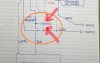
@merlynski , thanks for your patience with me. My sketch is based on what I saw at the underside of unit and trying to reflect what that is, see attached. The red arrow is that resistor, isn’t that blue arrow ground?
And also let me study what you said at the same time. I will not touch this until I feel totally understand and comfortable with it.
The unit sounds good but with this low star up 1 sec hum and I read it somewhere by NAD’s people naming it as the “welcome hum” and mentioning this could be the solution.
https://audiokarma.org/forums/index.php?threads/short-hum-at-startup-of-recapped-nad-3120.824710/EFCAD2B3-6590-455F-82E3-2CFA7F66C20F.jpeg
 
You are most welcome!
Yes, the blue arrow does point to the chassis (ground) connection. If you look on the SM schematic the wires for the transformer primary winding are labeled as yellow (to the fuse) and white (to the switch). The wire labeled BLACK is the one that goes to the chassis symbol in the schematic, and that goes to the chassis in your picture, is the shield inside the transformer. It has no connection to the primary or secondary windings, unless the transformer fails and shorts internally.. That kind of failure usually takes a lightning bolt or a lot of heat. I can see from the picture how the misunderstanding could arise.
If you already had the triac in place it might be the cause of a startup hum, but installing it would not get rid of it. The first post you made (#462) refers to a 'soft start mod', but, as 50 Green was correctly saying, this is not a soft start circuit. The protection circuit leesonic mentioned in the thread you got here from will stop a startup speaker hum.
If you are having a startup hum coming from your transformer it could be a couple of different things. As transformers age, the heating and cooling loosens the varnish between the plates and they can start to buzz, the higher current at startup that fills the empty power supply caps can make this audible. Excess current draw at startup could do it as well.
Looking over the schematic I don't see a mute function or protection relay to disconnect the speakers. Do you hear the hum from the speakers? If you want to deal with a hum issue start a new thread in the Solid State forum. It would be 'off topic' in this thread. Mention my name with the @ and I will jump in and help.
 
Last edited:
@EC1
@50 Green
I see a very dangerous situation in the drawings in the two previous posts, there is a direct connection between the primary side of the transformer and "ground":
View attachment 2033579

This may cause the chassis to be at the ac line voltage potential. View attachment 2033588
Also, the resistor that is shown in series with the transformer winding is incorrect. If that is the resistor shown in the SM as R901 3.3MΩ, it will block current through the primary, and the unit will never power up.
PLEASE discard that whole drawing as it is both dangerous and nonfunctional. I recommend deleting the drawing from the thread/posts entirely so no one mistakes it for a correct application of a triac installation.
Here is a copy of the AC primary side from the service manual:

View attachment 2033600

Here is how to correctly wire in the triac to your Onkyo:

View attachment 2033625
Point taken, merlynski. I should have corrected the other errors in EC1's diagram. I didn't bother because the triac is on the other leg, but as you pointed out, someone else might come along and, not knowing, rewire their unit to match. I deleted my original doctored version of EC1's diagram and replaced it with one showing those corrections.
Thanks for noting that.
 
@50 Green , @merlynski ,
These is C901 across each side of the switch on the original layout. And this C901 will be connected to MT1 and MT2 of the Triac based on merlynski sketch, but comparing to 50 green revised doctored sketch, this C901 will be connected to G and MT2, is this ok? Please accept my stupid question, I am just trying to follow through and clarify myself.
I know the original C901 is not shown on my sketch, but I assume it is across those “to switch” on my sketch.
Thanks.
 
The original purpose of C901 is to absorb a spike created when the switch was opened with current flowing. It is not needed with the snubberless triac, but won't hurt anything if it is across the triac (MT1 to MT2). It should not be left across the switch between the gate and MT2 connection, as (maybe) current leakage through it could trigger the triac.
 
I just did this mod on a Scott 380R receiver, which uses a double-ended power switch to turn on both sides of the AC current for some reason. I used one triac per section and it turned out great.
 
I just did this mod on a Scott 380R receiver, which uses a double-ended power switch to turn on both sides of the AC current for some reason. I used one triac per section and it turned out great.
Please post a schematic of exactly how you connected them. The European models (220/240 vac) switch both sides of the AC line because they can both be 'hot'.
 
I just wired up both sections of the power switch the way the triac is normally wired. The power switch is the kind that attaches to the back of the speaker selector switch, it just has two sections instead of one.
 
I just wired up both sections of the power switch the way the triac is normally wired. The power switch is the kind that attaches to the back of the speaker selector switch, it just has two sections instead of one.
Is the transformer primary between the two triacs?
 
Is your unobtainium power switch worth $5 and an hour or so of your time?
---------
Aside: I wonder what the shop rate X thread 24 pages is? DANG! :D

 
I just picked up a Sanyo Plus 55 and am in the process of cleaning the pots etc. The switch works, but has a reputation for wearing out, I wonder if I should do this mod now. This is the part of the schematic that shows the switch wiring.
switch.jpg
 
Back
Top Bottom