

You are using an out of date browser. It may not display this or other websites correctly.
You should upgrade or use an alternative browser.
You should upgrade or use an alternative browser.
Is your unobtainium power switch worth $5 and an hour or so of your time?
- Thread starter K7sparky
- Start date


cyto
Super Member
Thanks!! I was a licensed electronics tech in the 70s and can easily modify or build from a schematic. But I get nervous making design changes myself.
Thanks again merlynski

gpounce32768
Well-Known Member
Make sure the to-220 tab is electrically isolated (assuming the part you're using has an exposed tab). That means a mica/silpad and and isolation bushing for the screw (so it cannot touch any part of the tab, but still clamp it down).
cyto
Super Member
Yep I know that, used to be a repair tech, just wondered if that would work as an adequate heatsink surface.Make sure the to-220 tab is electrically isolated (assuming the part you're using has an exposed tab). That means a mica/silpad and and isolation bushing for the screw (so it cannot touch any part of the tab, but still clamp it down).
gpounce32768
Well-Known Member
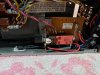
I think so... I mounted the triac via an existing screw thru an otherwise unoccupied corner of the rectifier board of the 100 watt Kenwood, so no good heat conduction. I put a heatsink on the triac- never got warm.

Bert Beukema
Well-Known Member
Hi guys,
I have both an SX-450 and SX-750 with the same symptoms. Perhaps this question is either moot or has been asked before. My machines are factory configured for 220 volts (Europe) and the power switches as well as the wiring are different. I am wondering if this triac solution is 110v only and what, if any, special arrangements I need to take for 220v.
Many thanks for your answers,
Bert

steve1953
Active Member
I am currently doing the double mod on a Scott 390R which is similar to the 380R. Does this look right to you ? Existing print :I just did this mod on a Scott 380R receiver, which uses a double-ended power switch to turn on both sides of the AC current for some reason. I used one triac per section and it turned out great.
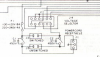 With mod:


TupolevFan
Super Member
The triac K7 uses has insulated metal tab meaning that tab is not electrically connected to any of device's pins. So no need for mica.Make sure the to-220 tab is electrically isolated (assuming the part you're using has an exposed tab). That means a mica/silpad and and isolation bushing for the screw (so it cannot touch any part of the tab, but still clamp it down).
Kicking an old thread.
Adapting R1 for 240Vac.
200-220ohms looks fine, note calculated resistance is a minimum, so round up a little.
https://www.littelfuse.com/~/media/...atic_switches_and_relays_application_note.pdf
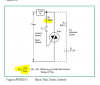
Adapting R1 for 240Vac.
200-220ohms looks fine, note calculated resistance is a minimum, so round up a little.
https://www.littelfuse.com/~/media/...atic_switches_and_relays_application_note.pdf
This installed cleanly and worked flawlessly with my Kenwood KR-4010, which even after thorough cleaning of the power switch, was flickering constantly. It drove me crazy. I just double and triple checked that I was putting the right wires on the right lugs because I didn’t want to blow this unit up (I’m a hobbyist restorer and by no means an electronic engineer).
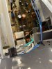
I found a nice spot on the chassis to mount the new circuitry, drilled a hole and tapped it with a machine screw, and added a dollop of heat sink compound, and it went in beautifully. This is a true game changer for these old flickering receivers, and it gave this one a new lease on life. Big thanks to the OP for this mod. It’s brilliant.

I found a nice spot on the chassis to mount the new circuitry, drilled a hole and tapped it with a machine screw, and added a dollop of heat sink compound, and it went in beautifully. This is a true game changer for these old flickering receivers, and it gave this one a new lease on life. Big thanks to the OP for this mod. It’s brilliant.

merlynski
Curmudgeon Electronicist
This installed cleanly and worked flawlessly with my Kenwood KR-4010, which even after thorough cleaning of the power switch, was flickering constantly. It drove me crazy. I just double and triple checked that I was putting the right wires on the right lugs because I didn’t want to blow this unit up (I’m a hobbyist restorer and by no means an electronic engineer).
I found a nice spot on the chassis to mount the new circuitry, drilled a hole and tapped it with a machine screw, and added a dollop of heat sink compound, and it went in beautifully. This is a true game changer for these old flickering receivers, and it gave this one a new lease on life. Big thanks to the OP for this mod. It’s brilliant.
View attachment 2172009 View attachment 2172010
 Be careful around those Triac connections, you have full mains AC available there in a very open and accidentally touchable position
 !
I strongly suggest you put some heat shrink tubing over the leads on the triac and the resistor.
I’ll follow your advice. Easy fix.View attachment 2172081 Be careful around those Triac connections, you have full mains AC available there in a very open and accidentally touchable position View attachment 2172084!
I strongly suggest you put some heat shrink tubing over the leads on the triac and the resistor.

50 Green
Well-Known Member
The heat shrink is well advised. Also not a bad idea to flow a little more solder on those connections when you re-do them.I’ll follow your advice. Easy fix.
They’re not taking solder well at all, and I’m concerned about cooking the thyristor, but I’ll try to get more on there. It looks worse in photos than in real life—the solder joints are quite solid and passed a good tug test.The heat shrink is well advised. Also not a bad idea to flow a little more solder on those connections when you re-do them.
50 Green
Well-Known Member
Are you using flux? What kind of iron? What heat?They’re not taking solder well at all, and I’m concerned about cooking the thyristor, but I’ll try to get more on there. It looks worse in photos than in real life—the solder joints are quite solid and passed a good tug test.
Rosin core 63-37 Kester solder, a new Hakko soldering station, running at 750 degrees F.Are you using flux? What kind of iron? What heat?
50 Green
Well-Known Member
Perhaps a little additional flux, applied prior to applying heat, might help the solder flow better.
Heat to the triac shouldn't be a concern, but you might try tinning the wires (especially the one with the light blue insulation) prior to attaching them, if you want to be extra cautious.
Heat to the triac shouldn't be a concern, but you might try tinning the wires (especially the one with the light blue insulation) prior to attaching them, if you want to be extra cautious.
All wires were tinned, those solder lugs on the triac are just very stubborn.Perhaps a little additional flux, applied prior to applying heat, might help the solder flow better.
Heat to the triac shouldn't be a concern, but you might try tinning the wires (especially the one with the light blue insulation) prior to attaching them, if you want to be extra cautious.