• The move to the new server is done. There are some software and database maintenance updates in process. This has us passing the hat around to help out. We appreciate any donations. Seriously, even a dollar helps. The payment page may be found here - https://www.audiokarma.org/support.html

Is your unobtainium power switch worth $5 and an hour or so of your time?

Hello all, I’m wanting to do this mod to a Sony STR-7065 along with many others, but this is my first go at it so I want to make sure I’m doing this correctly. I bought several T3050H-6T triacs. These are subberless and are not isolated, so I’ll have to use an insulator to mount it to a heatsink.

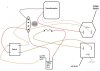
I don’t know why, but I had to draw it out myself. Here is the original wiring.
073FF019-D4D9-414C-9EE9-2D7313EFD34F.jpeg

and I’m switching it over to this correct?
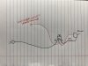
8E011701-8A79-42DE-BB82-32A321D9453A.jpeg

Should I remove this capacitor that’s wired across the switched and unswitched outlets on the back?
33C008AE-6A89-4B00-8275-170790E12BA7.jpeg

After making sure that I have the wiring correct id like thoughts on mounting. Not too many places to mount this and not entirely sure how warm this will get. It’s not like the 7065 is a current monster. I want to do this to my pair of Kenwood 700Ms and figure they’ll get a bit warmer. Anyways, I’m thinking the side by the switch

292A54AB-5FED-420C-AF5F-A434F50DB7DB.jpeg

or would the bottom floor be better? I figure the floor may have better heat sinking, but don’t know if I’ll need it.
C2E8E294-D9AF-443A-8C92-444FEFE4FB70.jpeg

Any thoughts on my questions would be greatly appreciated!

Thank you,
Dan
 
It appears you have everything correct.

As for mounting, I'd choose what would be the largest heat sink. Probably not necessary, but no harm in extra margin. I'd also try to keep the AC wiring as close to its original location as possible, to avoid putting it somewhere where it might induce hum.
 
It appears you have everything correct.

As for mounting, I'd choose what would be the largest heat sink. Probably not necessary, but no harm in extra margin. I'd also try to keep the AC wiring as close to its original location as possible, to avoid putting it somewhere where it might induce hum.

Great, thank you for the advice! What are your thoughts in the capacitor across the switched and unswitched outlets? It mentions in the instructions in the first post “remove RC snubber across switch contacts”. The wires from the switch do end up at those outlets, so that cap does indeed go across the switch contacts. Would that be considered the RC snubber?

Dan
 
Sorry if that wasn't clear. I had inferred that in saying you had everything correct. That is the RC (Resistor Capacitor) snubber and not needed with a "snubberless" triac. You might want to hang on to it, in case you ever want to return to using the switch only.
 
Great, thank you for the advice! What are your thoughts in the capacitor across the switched and unswitched outlets? It mentions in the instructions in the first post “remove RC snubber across switch contacts”. The wires from the switch do end up at those outlets, so that cap does indeed go across the switch contacts. Would that be considered the RC snubber?

Dan
The snubber across the switch contacts should be removed, as any leakage through it might trigger the triac. With the triac in place the switch does not need a snubber to protect it. A cap across the AC socket is to reduce rf on the power line. I won't make any difference to the triac. However, it should be an XY safety cap, if it is not you should change it to one.
 
The snubber across the switch contacts should be removed, as any leakage through it might trigger the triac. With the triac in place the switch does not need a snubber to protect it. A cap across the AC socket is to reduce rf on the power line. I won't make any difference to the triac. However, it should be an XY safety cap, if it is not you should change it to one.
Excellent advice, in general, however in saabracer23's case, the device in question is a resistor/capacitor snubber (not a capacitor only) and although it is physically attached between (not across) switched and unswitched outlets, electronically, it is across the switch contacts.

upload_2021-8-11_12-55-33.png
 
Last edited:
The snubber across the switch contacts should be removed, as any leakage through it might trigger the triac. With the triac in place the switch does not need a snubber to protect it. A cap across the AC socket is to reduce rf on the power line. I won't make any difference to the triac. However, it should be an XY safety cap, if it is not you should change it to one.

Excellent advice, in general, however in saabracer23's case, the device in question is a resistor/capacitor snubber (not a capacitor only) and although it is physically attached between (not across) switched and unswitched outlets, electronically, it is across the switch contacts.

View attachment 2312405

Excellent advice, thank you so much. Would a good move be to remove it and then place safety cap in its place? I have some .01 uF xy rated caps.

Dan
 
Excellent advice, thank you so much. Would a good move be to remove it and then place safety cap in its place? I have some .01 uF xy rated caps.

Dan
You do not want anything that might conduct across the switch contacts when it is open, as noise or voltage spikes might trigger the triac when you do not want it. The current through the switch contacts is quite low, just gate current for the triac, so the switch does not need any 'protection' when the contact breaks. Normally the RC snubber absorbs the inductive kick from the transformer when the switch opens (with no triac in place). The triac controls the mains power on and off, the switch just carries the small gate current, after the triac is installed.
 
Last edited:
Excellent advice, thank you so much. Would a good move be to remove it and then place safety cap in its place? I have some .01 uF xy rated caps.

Dan
NO. Do not put anything in its place.

A safety cap should never have entered this discussion. It did purely by accident. You mistook the snubber for a capacitor and mistakenly said it was "across" the outlets. merlynski then gave advice about a capacitor across an outlet ("AC socket" as he put it.) That advice was based on the original misinformation and has no bearing on the receiver you're working on.

There is no capacitor across any outlet and there is no need for one (nor should one be across the switch.)

As can be seen in the portion of schematic I posted (and as I said earlier), although the snubber is physically attached between two outlets, electrically, it is across the switch. It's there to suppress voltage spikes when the switch is opened but is not needed with a "snubberless" triac. Remove it and save it, to have in case you decide to return to the original configuration. Do not put anything in its place.

 
You do not want anything that might conduct across the switch contacts when it is open, as noise or voltage spikes might trigger the triac when you do not want it. The current through the switch contacts is quite low, just gate current for the triac, so it does not need any 'protection' when the contact breaks. Normally the RC snubber absorbs the inductive kick from the transformer when the switch opens (with no triac in place). The triac controls the mains power on and off, the switch just carries the small gate current, after the triac is installed.

Okay great, that was my question, as to if it was a snubber. I 100% thought it was a cap. I didn’t see any safety ratings on it so wasn’t sure if it was a safety cap, but I should have looked at the schematic and seen that there was a small resistor in there as well.


NO. Do not put anything in its place.

A safety cap should never have entered this discussion. It did purely by accident. You mistook the snubber for a capacitor and mistakenly said it was "across" the outlets. merlynski then gave advice about a capacitor across an outlet ("AC socket" as he put it.) That advice was based on the original misinformation and has no bearing on the receiver you're working on.

There is no capacitor across any outlet and there is no need for one (nor should one be across the switch.)

As can be seen in the portion of schematic I posted (and as I said earlier), although the snubber is physically attached between two outlets, electrically, it is across the switch. It's there to suppress voltage spikes when the switch is opened but is not needed with a "snubberless" triac. Remove it and save it, to have in case you decide to return to the original configuration. Do not put anything in its place.

Did I explain its position incorrectly? I provided a pic and said that it spanned across the switched and unswitched outlet, which also happens to be across the switch contacts at the same time. I ask so that if there is ever a situation where I need to describe something similar I can do it in a less confusing way. Hopefully I won’t have to.

Excellent info and I want to thank both of you and others for their assistance in this thread. I just did a bunch of reading on a small circuit that helps you design the perfect snubber for your particular unit. Figure with how hard some of these switches are to get you might as well do this option most of the time.

Dan
 
Okay great, that was my question, as to if it was a snubber. I 100% thought it was a cap. I didn’t see any safety ratings on it so wasn’t sure if it was a safety cap, but I should have looked at the schematic and seen that there was a small resistor in there as well.
If you look at the snubber itself, both the capacitance and the resistance are printed on it (separated by a "+" sign.)

Did I explain its position incorrectly? I provided a pic and said that it spanned across the switched and unswitched outlet, which also happens to be across the switch contacts at the same time. I ask so that if there is ever a situation where I need to describe something similar I can do it in a less confusing way. Hopefully I won’t have to.
The word "across" is what caused the confusion. In an electrical circuit, connecting something "across" implies it's connected to both terminals (or leads) of a device (or devices.) That could be the + and - leads of a component (say, a capacitor) in a DC circuit, or in the case of your receiver, "across the outlets" would imply it was connected to both the "hot" and "neutral" sides of both AC outlets.
 
If you look at the snubber itself, both the capacitance and the resistance are printed on it (separated by a "+" sign.)


The word "across" is what caused the confusion. In an electrical circuit, connecting something "across" implies it's connected to both terminals (or leads) of a device (or devices.) That could be the + and - leads of a component (say, a capacitor) in a DC circuit, or in the case of your receiver, "across the outlets" would imply it was connected to both the "hot" and "neutral" sides of both AC outlets.

Once I snipped it out, I did indeed see the 120 ohms printed on it. I should have taken a closer look.

What you say makes total sense, if I say I’m going to measure the voltage drop across a resistor then I’ll put a lead of the DMM on each leg of the resistor. That certainly is confusing. Thank you again!

Dan
 
Yes, unlike some fields where an entirely new vocabulary is created, a lot of common, everyday words are given very specific meanings in electronics. It's not too difficult to say something entirely contrary to what's meant, merely by using simple language (if unaware of the specific denotation of the term in electronics.)

As an interesting aside (and hopefully not too much thread drift) that snubber is still available new (although backordered at the moment.)
 
Yes, unlike some fields where an entirely new vocabulary is created, a lot of common, everyday words are given very specific meanings in electronics. It's not too difficult to say something entirely contrary to what's meant, merely by using simple language (if unaware of the specific denotation of the term in electronics.)

As an interesting aside (and hopefully not too much thread drift) that snubber is still available new (although backordered at the moment.)

Goodness that snubber is expensive! Wouldn’t it be cheaper to just make it yourself using two separate components lol.

Got the triac wired in and mounted, screwed to the flood of the chassis. This ensures a nice chunk of metal to draw heat from it.

I used a sleeve for the screw shaft to go through and a mica insulator to install it. Measuring from the mounting tap to the screw I am seeing some resistance, but my guess is through the circuitry? It’s quite high at about 20 meg from ground to the mount (or MT2). Does that seem reasonable?

Dan
 
Well it seems I was too worried about getting it the most heat sinking possible when it didn’t need it lol. I could have mounted it in a much more convenient location with bit less mass to mount it to. I wired up a pair of MB Quart 220s which are a 4 ohm 6-1/2” two way. Not sure about efficiency, but they’re no Klipsch. I turned the volume up to a pretty darn loud level to where I was measuring right around 1 amp current draw at the power plug. I let it play for close to 2 hours at this level and I couldn’t feel any warmth at all on the mounting position of the chassis. I’m guessing not too surprising with 1 amp draw, I’m sure if it was closer to the 30A the triac is rated it would have been much warmer. The output heatsink was fairly warm though. This is an awesome new idea to have learned, thank you all. This new Sony power switch should last forever. The original was rated for 10 amps, so they must have plugged in a toaster or something to the switched outlets lol. Now off to save a pair of Kenwood 700M switches!

Dan
 
I wanted to mention one thing that might be relevant to an earlier post. Someone was talking about using two triacs to simulate the European standard of a DPDT switch. I don't think that will work. I'm pretty sure that both MT1 and MT2 need to have voltage present in order for the gate to trigger. If you use two, which will place them effectively in series, each one turns off power to the other.

Hopefully, one of the members with more experience can address this concern.
 
The Q4025L6 is obsolete at Mouser and is no longer stocked. They normally carry the Q4025L6TP, but that is out of stock until 2/1/2022, and I believe that has the non-isolated tab, so you'd have to use an insulator. Is there another similar triac that can easily sub for the Q4025L6?
 
Search for an in-stock triac with the specs you need and you should come up with something. Here's an example of a snubberless, insulated tab triac that might work, if it meets your required specs.
 
So the STI one recommended earlier in this thread (not the NLA original) with insulated tab is what I just used on my MAC1900. In addition, it keeps full load AC out of the rotary switch which is also volume. . There was a distinct reduction of residual hum. I had just finished a total recap and replacement of key transistors in the 1900, so this was the piece d’resistance to finish the amp. This old 1973 receiver has a combination of point to point wiring and “new” modular plug in cards so adding the little wiring as shown looks practically factory, except for the heatshrink. I used a flameproof 1/2W 100 ohm resistor.

I clipped out the original pair of .005uF ceramic caps and resistor that were wired to ground and were used as a snubber at the utility outlets. I would only ever plug in a turntable to the receiver AC (keeps grounds the same) so negligible load. Those old outlets only take two prong non polarized anyway, so only old turntables can be used.

Super easy and intelligent mod, IMHO.
 

Attachments

  • 5BEACADD-0CB7-48CA-99F6-542F4FE71FD7.jpeg
    5BEACADD-0CB7-48CA-99F6-542F4FE71FD7.jpeg
    172.2 KB · Views: 85
Last edited:
I have a European machine and tried implementing it using the schema attached (from an earlier thread).
However when I power the machine on the transformer starts humming like crazy. That's not right at all.
When I put it on my dim bulb there is no problem at all.
The Triac I used is a Littlefuse Q4025J6TP (of course it is isolated).

Who can tell me what went wrong here?
 

Attachments

  • SX 750 TRIAC wiring.JPG
    SX 750 TRIAC wiring.JPG
    46 KB · Views: 77
Back
Top Bottom