When I had my Dynaco MKIIIs, I built a relay switch box to turn them on, locating them by the speakers.I think most modern, decent quality switches should be able to handle that amp...my understanding of the triac mod is to assist underqualified switches (mainly the ALPS, it seems) from buying the farm, so that the piece is still, essentially the same, with something added. Also the offending switches tend to be a rotating selector type, and I'm not sure if they're even made anymore, and why would they? They suck.
In your case, you're in control of the selection of switch, I'd say just pick a good one with the appropriate specs.
There've been a lot of posts about a speaker relay, and that may also be something to consider


You are using an out of date browser. It may not display this or other websites correctly.
You should upgrade or use an alternative browser.
You should upgrade or use an alternative browser.
Is your unobtainium power switch worth $5 and an hour or so of your time?
- Thread starter K7sparky
- Start date

McFork
New Member
My Marantz 16b has no switch, and I just put one of those inline on the power cord types. Sits just a bit back from the front of the amp, not really visible. but easily reachedWhen I had my Dynaco MKIIIs, I built a relay switch box to turn them on, locating them by the speakers.
Am going to build myself a VU box at some point, and probably include a switching set up. Love that amp.


francisleo75
Member
Good deal! I'll try itI finally got around to trying a Triac to turn on and off an amp and it was a success. I am still looking for the down side of this mod.
This mod should work on any amp and the power switch load will be reduced to around 120 ma and no arcing. The power switch will now last longer that you will.
The test bed is a Lafayette LR9090 (Setton RS) series known for lunching on power switches. This switch had the NO contact for power "on" inside the switch gone, just smoky residue left. This special case required a relay NC contact for the PA Mute / protective relay dump on power "off". I moved the switch NC contact to NO position for the power on function.
Triac used was a Littlefuse Q4025L6 (Mouser 576-Q4025L6) Rated 400VAC 25A RMS for highly inductive loads and tab isolated. Way over rated. Yea olde Fluke gives around 7A AC peak on the 100 ms scale at power "on" and idle current of 0.6A AC at low volume. The Triac data sheet is on Mouser: http://www.mouser.com/Search/Refine.aspx?Keyword=q4025
Note: Triac suffix L6 is a TO220 case isolated tab, if you prefer solder loops for a buck or so more the J6 suffix is a TO218X with loop leads and isolated tab.
For me, the isolated tab and not having to bother with mica and screw isolator is worth a buck or 2. You?
This is a difficult mod with an extensive parts list:
1 ea Triac
1 ea 100 ohm 1/2 watt resistor
Remove the AC line power and transformer lead (and maybe switched rear outlet) from the power switch. Remove the RC snubber across the switch contacts.
Mount the Triac in any handy location.
AC power lead goes to M1
Transformer lead (and maybe switched rear outlet) goes to M2
Power switch:
lead 1 100 Ohm resistor and goes to gate G
lead 2 goes to M2
View attachment 1602421
OK!, so I lied about being expensive & difficult
I found a place on the chassis for the Triac that the leads would fit, drilled a mounting hole, soldered directly to the TO220 leads and used heat shrink over joint and lead.
Initial testing was done by removing the transformer primary fuse and hooking up a 100W bulb for a load. After a bunch of switching the bulb on and off, I put the transformer fuse back in and tested and tested...... The amp has been switched on & off left on for days and no problems.
On state voltage drop is 0.8 to 0.9 VAC which agrees with the data sheet curve
Other benefits / thoughts:
1. Littlefuse calls these Triacs: Alternistor Triacs and they are designed for high inductive loads so no RC snubber is required.
2. Power "off" is always at a zero crossing so there is no arcing thus no voltage transients inside the amp to worry the power supply components.
3. Power "on" has no contact bounce arcing. It did not seem useful to add the extra parts for zero crossing turn on.
4. A 200V rated Triac would work, but why save a few pennies and give Murhpy a chance?
5. Lower current rating would work. 3000W @ 125 VAC switching capability is not needed, but see above
6. Triac off state leakage is 50 micro amps which is lower than the original RC filter across the power switch.
7. A MOV and / or RC filter on the incoming power is still necessary to protect the amp from the rest of the world.
After more testing this mod will be refined with pictures and added to the LR9090 repair / upgrade thread.
I hope to get some feed back about possible problems I have missed.

Oldskoolfan
Active Member
Did this mod on a PL400 which everyone knows, didn't even have an on/off switch. But it does now. 
How did you rig it up?Did this mod on a PL400 which everyone knows, didn't even have an on/off switch. But it does now.
Oldskoolfan
Active Member
I'll get a parts list and drawing made up. Then I'll post it here.How did you rig it up?
I've got a couple of applications. Trying to do something coolI'll get a parts list and drawing made up. Then I'll post it here.
PL400 what?Did this mod on a PL400 which everyone knows, didn't even have an on/off switch. But it does now.
Oldskoolfan
Active Member
Phase Linear 400. Full WOPL upgrade with meter range switching and variable input gain mods.PL400 what?
Attachments

I know Pioneer made a PL-400 turntable too and was thinking why would you need anything like that on a turntable. LOLPhase Linear 400. Full WOPL upgrade with meter range switching and variable input gain mods.
Oldskoolfan
Active Member
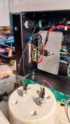
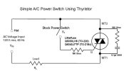
Here's some pics to start. I'll add some text in a bit.I've got a couple of applications. Trying to do something cool
Everything in the pics and the diagram should provide all the data you will need. The part number for the triac is a bit obscured. It is Q4040J7.
2 things I did differently;
1. I did not put in the snubber circuit. No need for it.
2. I broke the circuit between the fuse and the Hot lead of the transformer to install the triac mod. On the diagram the fuse would be before the tie point for the switch. Transformer T1 would be located where Load RL is.
Attachments


Last edited:
This is exactly what I want to do.Here's some pics to start. I'll add some text in a bit.
Everything in the pics and the diagram should provide all the data you will need. The part number for the triac is a bit obscured. It is Q4040J7.
2 things I did differently;
1. I did not put in the snubber circuit. No need for it.
2. I broke the circuit between the fuse and the Hot lead of the transformer to install the triac mod. On the diagram the fuse would be before the tie point for the switch. Transformer T1 would be located where Load RL is.
Looks pretty goodHere's some pics to start. I'll add some text in a bit.
Everything in the pics and the diagram should provide all the data you will need. The part number for the triac is a bit obscured. It is Q4040J7.
2 things I did differently;
1. I did not put in the snubber circuit. No need for it.
2. I broke the circuit between the fuse and the Hot lead of the transformer to install the triac mod. On the diagram the fuse would be before the tie point for the switch. Transformer T1 would be located where Load RL is.
Update: Works like a charm. Just like downtown. I've got two standard C12s to do once my current backlog is run down.
Attachments

Last edited:
Only reason I put it before the fuse was it was easier wiring. If the TRIAC shorts it is just like connecting 2 wires. If something BAD happens in the AMP that draws lots of current it probably doesn't make any difference. If there is an event that would short the TRIAC a standard fuse like in the picture (or any fuse of that size) is WAY to slow (burn curve Current vs Time) to protect any solid state device. Solid state protection fuses cost a hand full of TRIACS and even at that may not be fast enough.
Switching one side of the line with a physical switch (purple line in post 332) and the other side with a TRIAC is an unknown quantity. I've never tried it, never will and know no one that has tried it. Contact timing on switches and relays make / break in ms timing per contact is an art form of it's own.
In over 30 years I have never seen a TRIAC gate resistor blow in a correctly wired circuit. I suspect connection in post 332 is straight across not X as depicted and would explain the fried resistor

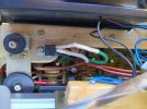
I have a little time where I can finally get back to rebuilding my Pioneer SX-750. I just finished working on the tone board and since I had access to the power switch I thought now is the time to put a triac in (alternistor on my case).
I did a lot of searching in this thread and after comparing some diagrams I finally found what I needed to do. I made up a diagram for the SX-750.
If you're going to use a triac, keep the snubber cap. If using an alternistor, remove it.
I was able to mount the alternistor to the chassis just in front of the transformer.

I did a lot of searching in this thread and after comparing some diagrams I finally found what I needed to do. I made up a diagram for the SX-750.
If you're going to use a triac, keep the snubber cap. If using an alternistor, remove it.
I was able to mount the alternistor to the chassis just in front of the transformer.
Last edited:


martin_pjr@y
New Member
Hi All, Great thread. I recently acquired a Realistic STA-85 that has a power switch like the Pioneer SX-x50's series that shares duty with the speaker selectors. I was initially hesitant of these models for the problems with the power switches but ended up pulling the trigger on this one anyway. The the receiver sounds good and all and looks beautiful but suffers from the dial lights flickering that seem to be the tell tail sign of these power switches arcing. I re-lamped it and would like to future proof the power switch and this thread seem to be the mod to do that. I modified the diagram from the service manual best I could and wonder if any of you could look at it and give me your input. Would you do anything differently or use one triac or the other? Also the plug is non polarized but from what I gleamed from this thread is it doesn't really matter, is that correct?
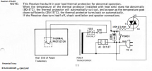
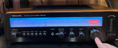
Attachments

Last edited:
martin_pjr@y
New Member
Thanks, Also I assume that CR851 can be removed. Its labeled on the schematic Spark Killer.If it's not a misprint, you need to cut at the red mark. Else looks ok from here...
View attachment 3160103
Does this look better?

Last edited: