turnitup
No, the stereo won’t break the crystal...Oh CRAP!
A little better schematic, with a couple of part numbers that I've sourced, even though the only part I've used so far is the smaller TO-220 part. Still, I had a Kenwood KA-8100 here with a fried power switch and after managing to get the switch working well enough to trigger the triac, installed the device as shown in the attached schematic and it works like a champ.
I'm working on a couple of Yamaha B-2's next, and plan on adding this mod in a similar fashion.
Edit: The server is barfing pine needles at the moment, so I can't get the schematic uploaded. I'll edit this post with the scat as soon as the server is officially 'out of the woods'.
Edit 2: Got it...I think...
Edit 3: Got a few Q's on this, so I'll mention this here...the location of the load (at MT1 or MT2) is not important...Littelfuse makes that clear in their application notes. But, triggering should always take place between the gate and MT2 (and even this may not be critical, but I prefer to follow at least one standard).
I am handy and brave with a solder iron, but am technically illiterate in reading electronic schematics (even as simple as this one from EchoWars), can someone fill in the blanks for me as to where the resistor goes, also looks like there is a cap in the mix. Size rating would also be nice...thanks.
I've got a 70's Akai receiver with an arcing power switch that I want to try this on. Awesome remedy!
Sorry, the original schematic is on page 3 of this thread.
Last edited:


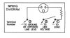
 is the light? If so, this mod will work a treat.