nasinn
New Member
Hi markd51, thanks for that will study it in detail. Kits have arrived at the post office so I'll pick them up after my holiday and report back on the progress.
On the topic of the crossovers I just got a oscilloscope / signal generator and had a bit of a play with one of the speakers. What I did was feed through my amp a sine wave of different frequencies and recorded the peak to peak voltages of the input terminals and of each of the driver terminals. The scope does not have one of these automatic response plot generator so it was a bit of a manual changing of frequencies and noting the Vpp values. With this Vpp information of the input vs. the drivers I did the voltage gain https://en.wikipedia.org/wiki/Gain_(electronics) plot, see below. One not is I don't think I was quite at the center of the brilliance / presence pads, but I can redo this all if there is any value in this sort of analysis.
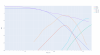
In addition to those measurements I also set up the crossover schematics in KiCad and ran a spice simulation of the frequency response and added to the plot results I was a bit unsure on the L4 connection as the original schematic has some strange inductor symbol (I am not an electrical engineer - so I am keen to hear what that means but my googling tells me its a tapped inductor but it was not clear to me where to connect the R7 to, but the sim did not ran when I connected it at the bottom of L4).

Not sure what the value of all this is, or if I was just keen on trying out the oscilloscope haha... My hope would be that this could give some indication of the state of the caps, but I am very keen to get some input on this stuff from someone with experience in this sort of stuff.
Cheers,
Jonas
On the topic of the crossovers I just got a oscilloscope / signal generator and had a bit of a play with one of the speakers. What I did was feed through my amp a sine wave of different frequencies and recorded the peak to peak voltages of the input terminals and of each of the driver terminals. The scope does not have one of these automatic response plot generator so it was a bit of a manual changing of frequencies and noting the Vpp values. With this Vpp information of the input vs. the drivers I did the voltage gain https://en.wikipedia.org/wiki/Gain_(electronics) plot, see below. One not is I don't think I was quite at the center of the brilliance / presence pads, but I can redo this all if there is any value in this sort of analysis.
In addition to those measurements I also set up the crossover schematics in KiCad and ran a spice simulation of the frequency response and added to the plot results I was a bit unsure on the L4 connection as the original schematic has some strange inductor symbol (I am not an electrical engineer - so I am keen to hear what that means but my googling tells me its a tapped inductor but it was not clear to me where to connect the R7 to, but the sim did not ran when I connected it at the bottom of L4).
Not sure what the value of all this is, or if I was just keen on trying out the oscilloscope haha... My hope would be that this could give some indication of the state of the caps, but I am very keen to get some input on this stuff from someone with experience in this sort of stuff.
Cheers,
Jonas
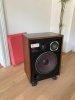
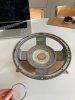
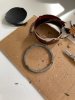
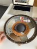
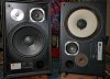
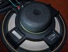
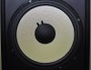
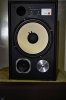
 Other than that the foam was OK, not great but will let it be for now. The cabins are quite damaged so I will give them some love and maybe write up a post on that somewhere here, then the idea is to make a speaker selection switch as my amp does not have one (should be okay to have it as a parallel connection with A / B / A + B as both sets are 8 ohm and amp should handle 4 ohm), so I'll be able to enjoy some tunes in the kitchen - so lots of projects in the pipes.