• The move to the new server is done. There are some software and database maintenance updates in process. This has us passing the hat around to help out. We appreciate any donations. Seriously, even a dollar helps. The payment page may be found here - https://www.audiokarma.org/support.html

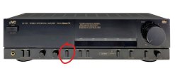
JVC AX444BK volume pot

billathome65

Active Member
Just picked up the system above was supposed to be no power up. However it fired up no problem. Only real issue is the volume pot is breaking down. Ive sprayed the hell out of it but if I can't sort that way I have 2 options dismantle and clean or replace. So has anyone striped this pot down succesfuly or second what part is a good replacement readily available.
 
Register to hide this ad
I'm unfamiliar with the JVC AX444BK. Seems adding more DeoxIT isn't gonna help. It appears you'll need to gain access to the inside of the pot to inspect the tracks at the very least, if that is possible.
 
Is that motorized?
Yes as far as i can see. I'll get a picture later. I've dug deeper now and found a couple of issues regarding the audio.

First i noted that adjusting bass and trebble made no noticable differance when turning the volume up the relay trips and then resets. Checking DC offset on

A speakers reads -23mV right speaker left -12mV .

B speakers -1mV right -2mV

Tapping the relay makes no real understandble differance.

As the B speakers are OK i'm thinking the output transisters are working OK

I have a basic Fnirsi DSO152 and probing the right A speaker it was jumping everywhere but tbh I am not sure what i'm doing with it currently so no idea what i'm looking at.

Ideas on where to go what to check?

This is a far superior amp than my current one so hoping to sort it.
 
Last edited:
this is tone on/off. give it a press and try to adjust bass/treble again.

View attachment 3826027

Spot on I should have made the connection as I mentioned the tone / mode switch. Yes that worked so that sides all working. So now it's the DC offset issue to track down. Could a faulty relay be the culprit or a bias issue? The amp volume is ok turned up slow but if turned up quicker the relay trips then resets.

Before I start desoldering any other ideas? Checked caps visually and see nothing of concern but it's a possibility.

Ideas lads.
 
Last edited:
Been doing some research regarding the relay tripping when the volume is increased quickly but OK when turned up slowly.

Initially there was a thought by me that the relay may be an issue? But researching the causative factors of the tripping stage one thought was the protection IC?

However as it trips when increasing fast, a suggestion is that rather than the chip or relay being the likely culprits as the relay only trips with sudden change of volume there may be an issue with either the output transistors or filter caps?

Rational for this is, when increased slow it does not trip but does when fast, and the sudden spike in current is to much to react to, and if the issue was the ic or relay this would not be a factor ie it would do it at any time.

Is the inbalance between the A speakers DC at -22mV and -2mV B speakers be a clue?

As even at -22 it's still within tollerance.
 
22mV is not enough to trip the protection relay. I would be looking closely at the PCB with a magnifier for cracked solder connections. I highly doubt the output transistors are bad. They would most likely fail shorted. If you can replicate the problem by turning the volume knob, I'd be looking closely where it connects to the PCB. I would also connect a mini grabber between the emitter resistor and speaker ground with the power off... One channel at a time. Power on, watch your DC offset while operating the volume knob. This eliminates the speaker relay and switches while trying to measure the offset.
 
The emmiter resister does not have a pin on top to connect and to close to board to get the clip to the legs only option is solder a wire to the board to grab that but atm don't want to be ripping the board out so seeing if i can remove the base to access. As you say the output transistor is not the likely cause based on the fact it would trip intermitently and not only when the volumes increased fast and allso fail short.

Measuring the dc offset at A speakers I see the numbers climb quite high when the volume is increased. As a diy setup I'm limited to what I can use to test effectively.

So we are saying output transisters not a likely cause. Tick them off the list.

possiible cracted joints.

The quick spike in power is the trip point so what within the system could cause it if we elliminate cracked joints.

I'm also currently ruling out the protection IC for the same reason as the outputs and as you say they would most likely fail short.

The relay is a possibility or the caps?

If I can access the emmiter resistors I'll check that as you suggest to elimmimate the Relay.

Just need to access the other side of the board..
 
Last edited:
I think the relay is doing its job. If you are seeing the DC offset rise by turning up the volume, this could be a problem. Although you are not sopped to check DC offset while playing audio. Does this unit have MAIN IN / PRE OUT jacks? If so, do you have something you could use as a preamp?
 
The emitter resistors have the same part number as my RX-950V receiver. They should have 3 pins through the top for connecting your leads to. They are .22 Ohm dual cement resistors.

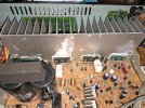
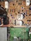
Can you post a picture of the inside?
 
The emitter resistors have the same part number as my RX-950V receiver. They should have 3 pins through the top for connecting your leads to. They are .22 Ohm dual cement resistors.

Can you post a picture of the inside?

You are totally correct I said there where no pins but there are, how I missed them is beyond me? I'm annoyed it's as though it just didnt register.

Does it matter which pin i grab? And how do i do the test? Grab lead from emmitter to speaker ground? Then how do i test with the DMM ie how do I probe? Do I just stick the probs in +&- again as you would do testing DC offset, whilst the emitter is bridged to the ground? And as it seams.to be the A side which emmiter to test? or just test from both?

BtW I can see the outputs have already been replaced and a messy job done so I need to clean that but it wasn't me making the mess.

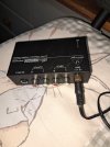
I do have a cheep Cambridge Audio amp I could use as pre amp but don't know how to use it as a test amp. Or I have a pocket phono pre amp pictured below?
 

Attachments

  • 20260830_062630.jpg
    20260830_062630.jpg
    162.5 KB · Views: 8
  • 20260830_062607.jpg
    20260830_062607.jpg
    176.6 KB · Views: 4
  • 20260830_062554.jpg
    20260830_062554.jpg
    185.3 KB · Views: 4
  • 20260830_065457.jpg
    20260830_065457.jpg
    119.4 KB · Views: 7
Last edited:
Back
Top Bottom