• The move to the new server is done. There are some software and database maintenance updates in process. This has us passing the hat around to help out. We appreciate any donations. Seriously, even a dollar helps. The payment page may be found here - https://www.audiokarma.org/support.html

JVC AX444BK volume pot

Went to make a start on replacing the caps earlier. First cap that came out I realised it was a 0.47uf cap at 100V which I thought I had ( errrrm nope ) and then noticed 2 of the caps are None polarized which I also don't have so another parts order gone in. .

On another note, I now have all the bits for another amp I had to put to the side, but it can wait as I want this one up and running first as I want to replace my old amp with this upgrade.
 
Very quick update.

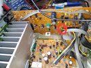
I've finished recapping the power / audio board but left the main filter caps in.

In a previous post I noted that 2sD1666 was running much hotter than the 2sB1133 transister.

Did a bit more digging and found the 2sB1133 had a near short between C & E loading more onto the 2sd1666.

Just waiting for the transistors to turn up then I can retest and hopefully the amp 9s working fine and I've not knackered it.

I've reflowed some joints as I noticed some cracked joints and i've increased the voltage of some of the replacement caps too.

Fingers crossed.
 
Ok guys just to let you know I have fixed the AX-444 as me tioned above I decided to change the caps as I was removing them to check anyway ( BTW all read near the stated tollerance ) I replaces the suspect transisters mentioned int he earlier ppst and can confirm this was the issue wirh the relay trip.

All I need to do now is remove the front panel to clean the switches as they are filthy. And I think the lights are dead to.

How easy is it to remove remove the panel i'm worried about the 3 plastic plugs that need removing from the top of the panel.
 
How easy is it to remove remove the panel i'm worried about the 3 plastic plugs that need removing from the top of the pane
Picture? If they are the small plastic rivets I think you are talking about, just use a pair of side cutters to get a grip under the edge and lift up. Then use a small needle nose pliers to pull the rivet. The other piece will likely remain in the hole. Carefully pull it out. When you reinstall. Carefully push the three (four?) legs back together so it will fit into the hole. The rivet will expand those pieces to lock it in place.
 
Been chasing up 2 additional issues audio issue with volume gravely then OK droping in and out not fully. Loosing the bass and trebble. I've sprayed the pots and had to drill the other switches to get contact cleaner into them and think i've narrowed the problem to the volume pot itself. So need to replace that. Its a 250KB X2 i've ordered a ALPS RK27 250KAX2 which i believe will work?

The other issue is there are no LEDs lighting up and can't currently track down the problem. Suggestions please.
 

Attachments

  • 20260918_141009.jpg
    20260918_141009.jpg
    100.7 KB · Views: 10
  • Screenshot_20260918_164224_AliExpress.jpg
    Screenshot_20260918_164224_AliExpress.jpg
    68.9 KB · Views: 6
Last edited:
I have no Idea. But as I won't be using a remote with this, would that be an issue?

I tried finding this exact volume pot online but had no luck as I believe they are obsolete?

I needed a 8 pin so it was a direct drop in allowing other functions to continue except remote hopefully. The info I have is this is a smooth pot which I want and is a good replacement.

I guess I will find out.
 
I just assumed anything built in the late 80s had a remote. Maybe this amp doesn't. You would see the motor attached to the volume control if it had one.
 
Hi guys been away on holiday for a few weeks. When I got back the new volume pot was here but when I put it in it wouldnt work correctly so I stripped the original pot and cleaned it and now the volume is OK .

I'm getting no noticable change when I turn the balance pot so need to look at that.

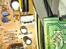
I'm investigating the control board pictured as the buttons and LEDs are not working when checking the IC it didnt appear to be getting power so I checked the connector from main board to control board 3 wires yellow and 2 blacks one black at point 3 gave no reading the middle black point 2 showed -0.995V and pin 1 yellow reads -555.1mV. I was expecting 0V at this point being I assume a ground wire.

I will take the board back out and check the solder joint make sure it's not a cracked dry joint. and hope this restores power to the control board if not what else to check for?

I tested the bridge rectifier diodes they are OK . It will be good if I can get this amp finished up.

Cheers guys
 

Attachments

  • 20261007_145018.jpg
    20261007_145018.jpg
    164.9 KB · Views: 8
  • 20261007_145023.jpg
    20261007_145023.jpg
    188.2 KB · Views: 8
  • 20261007_145104.jpg
    20261007_145104.jpg
    161.3 KB · Views: 8
Back
Top Bottom