• The move to the new server is done. There are some software and database maintenance updates in process. This has us passing the hat around to help out. We appreciate any donations. Seriously, even a dollar helps. The payment page may be found here - https://www.audiokarma.org/support.html

JVC AX444BK volume pot

Does it matter which pin i grab?
20260830_062630.jpg

And how do i do the test? Grab lead from emmitter to speaker ground?
chassis ground.

Do I just stick the probs in +&- again as you would do testing DC offset, whilst the emitter is bridged to the ground?
huh? no. there is a breakdown in communication here.

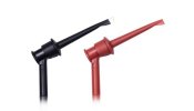
positive mini grabber to pin on resistor. negative mini grabber on chassis ground. set meter to dc voltage. that's it. that's your measurement. there is no other probing.

you will need to keep a close eye on the meter. it might happen fast, it might not. i would be using an analog meter fort this test myself.


I do have a cheep Cambridge Audio amp I could use as pre amp but don't know how to use it as a test amp. Or I have a pocket phono pre amp pictured below?

you don't need it.

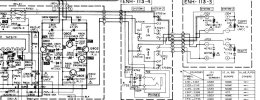
you need to do this test on both channels. if only one channel shows dc then that is the channel you concentrate on. if it is on both channels then it's likely to be a power supply issue. likely but not definitely. don't put on the blinders. you need to be aware of everything going on. jvc did a decent job with listing voltages in the schematic.
 
View attachment 3826657


chassis ground.


huh? no. there is a breakdown in communication here.

positive mini grabber to pin on resistor. negative mini grabber on chassis ground. set meter to dc voltage. that's it. that's your measurement. there is no other probing.

you will need to keep a close eye on the meter. it might happen fast, it might not. i would be using an analog meter fort this test myself.


you don't need it.

you need to do this test on both channels. if only one channel shows dc then that is the channel you concentrate on. if it is on both channels then it's likely to be a power supply issue. likely but not definitely. don't put on the blinders. you need to be aware of everything going on. jvc did a decent job with listing voltages in the schematic.
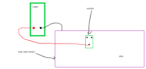
Just walk me through this a little you say

Positive mini grabber to pin on resistor. negative mini grabber on chassis ground. set meter to dc voltage. that's it.

Are you saying probe one pin pictured in circle with positive and other negative prob from one of the other pins on that resistor or to chasis ground. Normally its 2 outer pins so just clarifying as the layout of these emmitters are new to me.
 
Are you saying probe one pin pictured in circle with positive and other negative prob from one of the other pins on that resistor or to chasis ground. Normally its 2 outer pins so just clarifying as the layout of these emmitters are new to me.


positive mini grabber to pin on resistor. negative mini grabber on chassis ground. set meter to dc voltage.


amp.png

if you are using probes and not mini grabbers then stop until you acquire some mini grabbers for your meter.

Annotation 2026-08-30 105035.jpg
 
i have an ax66 that had a similar problem. i could never figure it out. i had to buy a parts unit and use a donor input pcb. that fixed it.

this unit is a bit different but close to the same era and i see some things that are similar.
 
I was only suggesting using a different preamp to see if the fault is in the preamp section or amp section. You mentioned turning up the volume causes the relay to kick out.
Thats right if i turn the volume slowly it does not trip but trips if i do it quickly. I appreciate the suggestion as its something else I can use to test. Expands my knowledge to as I say I have a cheep Cambridge audio or the phono preamp im supposing the cambridge would be the best choice? If so let me know how to set up. Cheers buddy.
 
i have an ax66 that had a similar problem. i could never figure it out. i had to buy a parts unit and use a donor input pcb. that fixed it.

this unit is a bit different but close to the same era and i see some things that are similar.
The thing that's confusing is how out of balance A speakers are to B i'm sure running it that way l9ng term wont be good for the system. As it's hopefully going to be my new personal amp all advice is welcome. I could farm it out and pay loads of money but then I learn nothing and kick myself.

Cheers buddy.
 
comparing between the 2 is pointless. jvc used some series wiring ****ery with the speaker connections it seems.


View attachment 3826741

that gives me a headache tracing thru the switches to the speaker outputs.
Still struggling to understand the schematic tbh couldnt work out the signal path. But i'm seeing it now from the attachement. I hear what your saying about comparing A & B but as id hopefully be seing -2mV across the board and whilst 22mV is still safe i'm just tring to work out why the difference and if the differance is a symptom or cause of the trip?
 
Last edited:
If you don't have 2 sets of speakers hooked up, you will not get sound. When you press SPEAKER A and SPEAKER B together the speakers are in series. I'm thinking this amp was one included in a rack system and not stand alone. This would explain a weaker power supply. My receiver was from 1987 and does not put speakers in series. I think I saw a 1988 date on the service manual.

So I think it would be best and forget anything you measured from the speaker terminals and connect to the single point on the emitter resistor and ground. Do this with the amp off so we don't go boom!
 
Cheers my current amp is A* B so understand the no sound aspect. I take onboard what you say about how that will affect measurement at speakers so will check from emmitters. Thanks for the guidance.
 
Quick update. On advice i have checked DC offset between emmitter resister and speaker ground. Left sits around -9 to11mv Right is sitting at - 23ish mV on turning the volume pot quick Left doesn't go more than 14mV befor settling back however the right spikes around 30mV befor settling.

Checked bias on both emmitters they are no more than 2mV.

So something on the board is not able to keep up with the sudden increase in power.

I'm thinking.
Protecrion relay is good
Protection IC is good
Output transistors are good.
Volume pot working as well as could be expected.

So possibilities
Leaking Capasitors.
Dry cracked joint ( tap test didn't highlight anything)
Faulty Zener?
Faulty transistor? Or mosfet i'm doubting the mosfet ( just because )

Am I going to have to remove the board to work on it or does the base open up to give access to the board?

If I can work on it in sittu brilliant which componants from the pictures to check first?????

Cheers guys.
 
Back
Top Bottom