• The move to the new server is done. There are some software and database maintenance updates in process. This has us passing the hat around to help out. We appreciate any donations. Seriously, even a dollar helps. The payment page may be found here - https://www.audiokarma.org/support.html

JVC JR-S 501 sound problem.

I was getting sound from the headphones but I did not try threw the speakers. If I tried hooking up the speakers would The iPod even be able to drive the speakers? Once again the amps volume/equalizer have no effect on the headphone volume. The only thing that changed the volume was the iPods volume.
 
Never mind my previous post.

So I tried useing some speakers instead of head phones. I did the same procedure except I used speakers instead of headphones. When I used speaker 1 I was getting nice and clear music from both speakers

When I switched to the Speaker 2 inputs the Music was noticeably Louder. I could even start to see the meters move a little bit.
image.jpg
 
I checked the both integrated circuits 501 and 502 and the results were interesting. I had to do it with an analog multi meter as I don't have a digital one, but I believe my analog one is accurate.

As you can see in this picture, the circled solder joints are the ICs connections to the board.
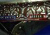
image.jpg

The ICs are Flipped around so these collor coded arrows show the voltages that are supposed to be the same.
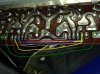
image.jpg

having the black prongs connected to ground and red ones testing the voltages

The solder joints connected by the black line both measured: 24.9 volts
The solder joints connected by the red line both measured: 21.9 volts
The solder joints connected by the blue line both measured: about .6 volts
The solder joints connected by the grey line both measured: 21.1 volts
The solder joints connected by the yellow line both measured: 21.2 volts
The solder joints connected by a brown line both measured: 24 volts
The solder joints connected by the green line both measured: 24.1 volts

Once again these measurements were taken with an analog multimeter so they may not be 100% accurate, but they should be close.

Also I do NOT know exactly what solder joint correlates to the PIN number. not sure how to find that out. It seems weird that almost all of the voltages on the diagram would expect negative voltages and I got all positive. Also only 3 of the voltages in the schematic are supposed to measure over 20 volts and for me all except for one measured over 20 volts, though the voltages were the same for both ICs.

 
Yea. I plan to get a better fluke digital multimeter in about a week so I will be able to test more things, but once again I believe this meter is pretty accurate.
 
Headphones don't load. You could have an open, not shorted, driver or output. A scope shows this up in a hurry.
 
Once again I tested it with speakers and I got the same results when bypassing strait to the power amp. I will be able to test the output transistors once I get a better multi meter.
 
When I tested all of the output transistors, I'd transistors, and powerboats transistors/caps it seemed everything tested out good.

It seems though that when testing threw the aux input I'm now able to get an audible volume when the volume is at about half way and up, but still nowhere close to what it should be.
I replaced the IC transistors, and DC power board Capasitors and transistors to be safe, but I'm still getting the same result. I'm currently looking at the sea equilizer board again. I ended up realizing that a Capasitors solder joint popped out of socket on the sea board, but when I resoldered it nothing happened. I ordered all of the correct sea Capasitors so we will see what happens when they come in.
 
redk is right I think, some of those voltages should be negative. This means probably that you have a bad regulator or connections thereto. Don't just crank it up and go pounding around there to find a bad connection, if it makes with the volume up it is going to put one hell of a pulse of DC into the power amp. I wouldn't want to do that.

Didn't study it all that much, but looks like maybe on the board labelled TPS-118A, your problem could be X802 or associated components.
 
TPS-118A is the DC power board. I already replaced all of the transistors and Capasitors on that board. I will recheck the sea board IC voltages when I can. I'm confidant that the transistors I ordered are real and not counterfeit, one concern I do have is the IC Transistors on the main amp board (x717-720). The new ones I ordered were from honkong and from the resurch I've done I'm a bit concerned so I will be ordering them again from Better seller with better looking transistors.
 
Fairchild KSA1220A / KSC2690A from DigiKey or Mouser should be perfect replacements for 2SB649A / 2SD669A .
 
Looking at the soldering the traces. I think you have cold solder joints. pics are alluding but that's a lot of solder and solder doesn't conduct like wire.

Just my opinion.
 
Over all there are quite a few cold solder joints that I have been repairing on the power amp board and DC power bored, I did a lot more re capping on the sea board and amp board but it is still the same result. The IC chips on the sea board are still giving out wierd voltages.

It would be nice if I could find a different sea board from some part unit to see if that's really the problem.
 
Hey all,

I recently purchased a JR-S501 and it appears to be having the same problem. Faint sound when cranked to full. Any updates or ideas as to what's causing this?

I should note, the power meters never show anything, but if you slide the the 40hz slider up and down they will jump a bit. Other than that, there's next to no sound.
 
Last edited:
Did you try bypassing the preamp and testing the main amplifier with a spliced AUX cord or equivalent?
 
Did you try bypassing the preamp and testing the main amplifier with a spliced AUX cord or equivalent?

Yep, and it appears the main amp is working correctly. Also noticed like you that the balance control still functions even if you bypass the preamp and equalizer.
 
Yep, and it appears the main amp is working correctly. Also noticed like you that the balance control still functions even if you bypass the preamp and equalizer.

Yea with all the time and resources I've spent on trying to diagnose the problem I still have not found it. I always had a gut feeling that the problem lies in the equalizer board but after replacing all capacitors in that board I still don't get anything.

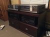
Also many of the people I know who know this JVC equipment very well say they never had a problem with the equalizer board So I doubt if that's the issue. Maby when I get the money I can find a deal on a jr s 301 on eBay and replace the sea board to see what happens. I currently have it on display with my other stuff because it's so beautiful. I also have a JR s 400 MK1 that I just recently won on eBay. The seller told said that it produced no sound but all it really needed was pre amp to main in jumpers.
image.jpg
 
Seems you have not been told so far that if experiencing the same issue on both channels, then it's most likely due to a power supply issue. Looks like you did not measure that yet.

What's the voltage output at TP 704 and 705? Remember your analog MM will not read negative values. You know it's negative if you need to reverse the leads. Be sure to find proper ground for the meter.
 
Back
Top Bottom