You are using an out of date browser. It may not display this or other websites correctly.
You should upgrade or use an alternative browser.
You should upgrade or use an alternative browser.
JVC JR-S 501 sound problem.

6taafondo
Pablo
Those values are somewhat deviated from specs, but still make sense.
You should read them also at 506 and 507 at TAC488B circuit board. Please check them out.
If this is OK, you may try injecting audio signal at 501 and 504. You'll be able to control the amp output with the volume pot so crank it up.
If you still get no (or super low) audio output we will continue from this point.
You should read them also at 506 and 507 at TAC488B circuit board. Please check them out.
If this is OK, you may try injecting audio signal at 501 and 504. You'll be able to control the amp output with the volume pot so crank it up.
If you still get no (or super low) audio output we will continue from this point.
6taafondo
Pablo
Please, read the voltage value at pins 4 and 8 of IC501 and 502.
Also, inject audio signal at pin 1 of IC501 and 502. Watch out as there's no volume pot control here. Use as signal ground the ground contact at any of the input connectors.
Be extremely careful not to make a short between pins when reading voltages or injecting signal.
Also, inject audio signal at pin 1 of IC501 and 502. Watch out as there's no volume pot control here. Use as signal ground the ground contact at any of the input connectors.
Be extremely careful not to make a short between pins when reading voltages or injecting signal.
Last edited:

ELzekio
Active Member
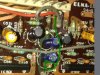
I've tested the pins on 501 and 504 a while back and the results are in this post. I got some weird values if I remember correctly. I tested pins 4 and 8 on IC 501 and 502 again and I got pin 8 reading around 26.3V. For pin 4 I got 25.03 volts if I remember correctly pin 4 is supposed to be negative which is weird.
Anyway, useing my aux cord I soldered the left and right channels to to the joints on pin 1 of IC 501 and 502 and when I put the signal threw I DID GET sufficient amplified signal just like I would have gotten if I plugged the aux leads in to 701 and 702 on the amp board. I also had NO severe audible distortion as I increased the input signal on my iPod.

Anyway, useing my aux cord I soldered the left and right channels to to the joints on pin 1 of IC 501 and 502 and when I put the signal threw I DID GET sufficient amplified signal just like I would have gotten if I plugged the aux leads in to 701 and 702 on the amp board. I also had NO severe audible distortion as I increased the input signal on my iPod.
6taafondo
Pablo
I've tested the pins on 501 and 504 a while back and the results are in this post. I got some weird values if I remember correctly. I tested pins 4 and 8 on IC 501 and 502 again and I got pin 8 reading around 26.3V. For pin 4 I got 25.03 volts if I remember correctly pin 4 is supposed to be negative which is weird.
View attachment 723950
Since the voltage value at 506 is correct (you read -22.6V) then there must be an interruption in the path to the trace joining pin 4 of both ICs. You should track down that broken path.
ELzekio
Active Member
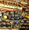
So do you think there is a good chance that the problem could lie in C550 and C549? I previously replaced those capacitors on the board. Looking at the top of the board I remember seeing something that looked like corrosion juice. As far as I know it looks like the solder joints look good.
Attachments

6taafondo
Pablo
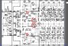
I'm quite sure this problem is not the caps. More, a trace, a solder, or a bridge; is there a through hole bridge joining both pc board sides just next to C549 marking? (looks like something is missing there.. a wire a bridge or something) Potential at TP506 is not reaching the ICs.
Check out the image attached.
Check out the image attached.
Attachments

ELzekio
Active Member
I CAN NOT BELIEVE IT!!!
I finally got this puppy running!
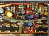
All I had to do was install a jumper to connect the ICs to the signal which is just like you said.
I always had a suspicion that I had an open circuit somewhere because when I unexpectedly won that JVC jr s 400 It would act exactly like the jr s 501. It would just give faint output when maxed out and that was because there was an open circuit (no jumpers from pre amp to amp)
One thing that really makes me wonder is when I got this 501 and opened it up, there was very little evidence of it being opened up and messed with. So it shocks me that somehow a jumper could have just dissapered from those two connection spots.
I finally got this puppy running!
All I had to do was install a jumper to connect the ICs to the signal which is just like you said.
I always had a suspicion that I had an open circuit somewhere because when I unexpectedly won that JVC jr s 400 It would act exactly like the jr s 501. It would just give faint output when maxed out and that was because there was an open circuit (no jumpers from pre amp to amp)
One thing that really makes me wonder is when I got this 501 and opened it up, there was very little evidence of it being opened up and messed with. So it shocks me that somehow a jumper could have just dissapered from those two connection spots.

JURB
Super Member
There was probably an alternative connection that went bad.
Had this with a car not long ago. Buddy told me to get it running he had to put in a fuse, but there never was a fuse in that slot before, but the car ran before.
I bet if you really really looked you would find a bad connection, but screw it, it works now. You know what they say - if it ain't broke don't fix it. It is so easy to slip up and fry out solid state equipment that it is best with the lid on it and running.
The car deal like this, we suspect there was a fusible link somewhere and it was meant as a tattletale. They wanted to know if it was going to fail. Surely all the authorized places got the memo, but nobody else. The fact that they wired it to the fuse box is telling.
Manufacturers do all kinds of strange things, for reasons that are hard to figure out. Some of them unfortunately are to ensure a breakdown, like when they put an electrolytic right near a heatsink n ****..
Enjoy the sound and forget about it.
Had this with a car not long ago. Buddy told me to get it running he had to put in a fuse, but there never was a fuse in that slot before, but the car ran before.
I bet if you really really looked you would find a bad connection, but screw it, it works now. You know what they say - if it ain't broke don't fix it. It is so easy to slip up and fry out solid state equipment that it is best with the lid on it and running.
The car deal like this, we suspect there was a fusible link somewhere and it was meant as a tattletale. They wanted to know if it was going to fail. Surely all the authorized places got the memo, but nobody else. The fact that they wired it to the fuse box is telling.
Manufacturers do all kinds of strange things, for reasons that are hard to figure out. Some of them unfortunately are to ensure a breakdown, like when they put an electrolytic right near a heatsink n ****..
Enjoy the sound and forget about it.
6taafondo
Pablo
Well done!  If you look close to that bottom open hole next to the C549 label, it seems that there goes a through hole bridge joining a path to the other pc board side. Also, your jumper is running parallel to a trace, so I guess that just by soldering a little wire on both board sides on that open hole would be enough.
As to why is a bridge missing there... the unit might have been sabotaged for a purpose...
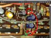
If you look close to that bottom open hole next to the C549 label, it seems that there goes a through hole bridge joining a path to the other pc board side. Also, your jumper is running parallel to a trace, so I guess that just by soldering a little wire on both board sides on that open hole would be enough.As to why is a bridge missing there... the unit might have been sabotaged for a purpose...
ELzekio
Active Member
Yea I can't thank you enough. Definitely been quite a learning experience.
I'm probably doing to do another recapping of this reciever. I recapped most of it but I was not educated on what capacitors I should get so this time I ordered audio grade Elna's instead of general Pourpose panasonics.
I'm probably doing to do another recapping of this reciever. I recapped most of it but I was not educated on what capacitors I should get so this time I ordered audio grade Elna's instead of general Pourpose panasonics.
Brealytrent
New Member
Sweet! I actually just dropped my receiver off at a local shop to have them look at it - I have a feeling this is the actual problem in my case as well. Gonna have to stop by and see if this is the problem on my receiver as well!
Brealytrent
New Member


We added jumpers to both traces that go around the capacitors as they were both severely corroded, one to the point of loss of continuity (the source of the problem). Both capacitors tested out fine and there were no signs of leaking, but they were both replaced anyways. Our only guess as to why this happens specifically at this one point and no where else (not a single sign of fault or leaking capacitors anywhere) is that they used some specific glue on the capacitors here that has broken down and become corrosive. I have a feeling that more JR-S501s or 401s are going to develop this issue over time. But for the time being, I'm going to start enjoying this receiver!

Brealytrent
New Member
There are two copper traces that go around the capacitors. I forget exactly why, but he decided to put the one jumper on the other side. I think it was since the surface was so corroded.