• The move to the new server is done. There are some software and database maintenance updates in process. This has us passing the hat around to help out. We appreciate any donations. Seriously, even a dollar helps. The payment page may be found here - https://www.audiokarma.org/support.html
Back for one last update on this pupper. Took me a while to get the time to buy new capasitors, but i finially got to recapping it with elna silmic 2 capacitors. After that all i had to do was piece back together the unit. Definitely harder then tearing it apart....

Now all that is left to do is give this thing a workout :). Ill be just giving it a light load with bob seger for a few hours.
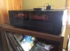
IMG_0629.JPG
 
Yea the display works fine, like i said there was a load of cold solder joints on the lcd , and other places around. Once i fixed those the glitches stopped.

Im able to adjust the idle current now. Along with fixing that open circut i think i was also having a hard time adjusting it because of that 30 pin ribbon cable that i had disconnected. Without this you wont get any sound from the reciever and other problems will occur, so it would have been best for me to make sure that is correctly installed before adjusting.
 
Last edited:
Hate to bump a thread, but for completion..
upload_2018-6-17_21-44-35.png
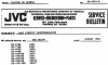
There was a service bulletin (SB-9002-B) released by JVC in August 1990 for this unit and others regarding the display. It states,
When the lamps burn out, diodes D497, D498, D499 short and burn the PCB. To prevent this from happening again, change the lamps and the three diodes. Use the new part number shown below and keep the diodes 1-4 inch or more above the PCB using a spacer on each lead.
Previous: MTZ12JC (500mW)
New: RD12FB3 (1000mW)

Or you could just clip the diodes out of the circuit and replace the bulbs whenever they go.
upload_2018-6-17_21-44-1.png
 
Alright, sorry. I kinda jumped the gun as those posts were omitted until after I was logged in. Think it has something to do with not wanting to display pictures until a user is logged into the site.

I like JVC's displays on their vintage units, but dang did they design the display circuitry silly, across loads of units, even more than that service bulletin. My RX-R76 has power meters and they designed two zener diodes to conduct if the backlight burns out to continue powering the power meter ICs, resulting in the zeners burning the board and shorting and taking out a resistor too. The solution is to just cut the two zeners out of the circuit and if the backlight bulb goes, just change it.. At this rate, if you have ANY old JVC reciever/amplifier have a look at the service manual and get rid of troublesome zener diodes before they cause harm!
 
I remember someone having an integrated amp with the same silly design. I guess the idea is to make the bulbs even brightness and if one burns out the other stay lit. It is poorly designed. I've often wondered why they just didn't specify a 8 or 12V tap on the transformer and wire the damned fuse lamps in parallel. Or like you say, just omit the zeners. The thing is that ALL lamps should be replaced if one burns out. But wouldn't you anyway since you are in there?
 
Hi, people.
A friend of mine gave me a RX-999V one year ago, but it had various issues from different points. Looking for answers, I've found this forum.
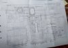
I've seen the PDF @redk9258 shared. It seems to be one part of the entire circuit, but it served me very well to solve part of the problems I had, and for that I'm very grateful. I wonder if you will be able to scan and share the board corresponding to the logical part (the one with the microprocessor - I'm sorry, I can't get to find any id on it to ease your search) to try to deal with the other issues.

Again, thank you so much.

Regards,
Carlos
 
Hi, people.
A friend of mine gave me a RX-999V one year ago, but it had various issues from different points. Looking for answers, I've found this forum.
I've seen the PDF @redk9258 shared. It seems to be one part of the entire circuit, but it served me very well to solve part of the problems I had, and for that I'm very grateful. I wonder if you will be able to scan and share the board corresponding to the logical part (the one with the microprocessor - I'm sorry, I can't get to find any id on it to ease your search) to try to deal with the other issues.

Again, thank you so much.

Regards,
Carlos
Hi Carlos. Where are you located?
 
I can't contribute to the technical discussion, but I did own one of these - and it sounded great. More than held it's own with my Pioneers and HKs. Looked great too - I never thought I would say that about a digital receiver of that era, but it really did look great. For such an early digital display, they did a nice job on it. At a glance the front fascia looks black, but up close you notice it was a really dark copper. Happy listening.
 
I can't contribute to the technical discussion, but I did own one of these - and it sounded great. More than held it's own with my Pioneers and HKs. Looked great too - I never thought I would say that about a digital receiver of that era, but it really did look great. For such an early digital display, they did a nice job on it. At a glance the front fascia looks black, but up close you notice it was a really dark copper. Happy listening.

No problem, thanks for your answer too. I think redk9258 has what I'm looking for. If you want, I'll keep you up to date.

Again, thank you.
 
Hi, redk9258. Thanks for your answer. I'm in Mar del Plata, Argentina
Hi Carlos.

I was going to drop the service manual in an envelope and send it to you. I see people have trouble getting packages in Argentina. Also, postage is unbelievably high.

I'm not really set up to scan the manual very quickly. I wonder how much an office store would charge to scan it.
 
Hi, redk9258.

I'm not in a rush. The amplifier isn't working well from one year ago more or less. It's a gift from an highly regarded person.

I want to thank you for the work you are taking with this. I know that you will do your best to make it ok.

PS: Here I had some doubts with my English. I hope you can understand what I tried to tell.
 
Hi, redk9258.

I want to thank you for the help you gave me to be able to fix the JVC RX-999V. The problem was on the surround section: the RY941 relay was the culprit, its coil cut.

Now I have to repair the FM tuner section: the stereo indicator isn't working.

I want to say Merry Christmas to all you. Again, thank you very much.


Carlos
 
Make sure there isn’t a cold solder joint where the display LCD thing connects to the circuit board. It would be best to redo every one of those joints as they will cause display problems.
 
Make sure there isn’t a cold solder joint where the display LCD thing connects to the circuit board. It would be best to redo every one of those joints as they will cause display problems.
Thank you so much, ELzekio. The thing is that also it has no audio when the stereo indicator is off. I think the issue is located in the 19kHz oscilator, but it becomes complicated for me to fix this not having that schematic.
Thanks to redk9258 I was able to repair several issues because he sent me other parts of the circuit.
 
Do you need the tuner section?
Hi, redk9258. As you could see, I was able to repair thanks to the circuits you sent me. Yes, I'll need also the tuner section. I don't want to bother you, but that will ease the repairs. I like this equipment so much, that's the reason I'm repairing it without thinking about the time I spend on it.

Again, thank you so much. Happy Holidays!
 
Back
Top Bottom