WattsAnOhm?
New Member
I just registered in part of this thread and lurking this website in general for a bit of time. Thank you in general to those helpful people out there.
This old thread gets a bump and I don't feel my specific situation is relevant to start a new thread.
The old hifi thing is somewhat new to me and I have aquired most of my stuff via dumpster diving. Though after clicking around here and there in forums and Youtube I unfortunately fell in lust with the JVC RX-1001V. I mean 89 buttons with most of which I will never need or use? Sign me up. Watched a few auctions on eBay and local platfroms come and go for prices I was unwilling to pay, until some guy an hour drive away listed one for sale but misspelled the title so I got it faily cheap and in proper working order (as far as I know).
Yesterday I pulled the top case to reveal maybe a decade or so of dust covering everything. But, someone had been in there at one point or another but I canot tell for what. The tie wraps holding the looms together are original and none of the screws show signs of being touched with a screw driver. Maybe to do a dust cleaning too. All parts look original, even the fuses.
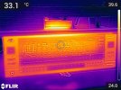
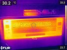
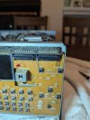
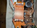
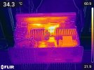
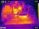
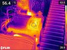
Being bored, I used my Flir thermal imaging camera and had a look around. There is quite the thermal gradiant in that case and componentry; a 50C spread. Maybe it is relevant to the display issue, but on the main amplifer board around ENH-071 behind the right side display are several small components that reach upwards of 90 degrees Celcius (Flir 21). That heat is soaking the board which powers and controls the right side LCD display (Flir 24 - lower part of picture). As shown in the pictures, the right LCD panel is notably hotter than the left panel (Flir 18, 19, 20 (20 - with top case off).
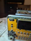
All was good until I carefully cleaned out the dust and reinstalled the protective cover, now my right side display is doing a flicker dance. Sometimes the display reads "PHONO" sometimes "HONO". Good times.
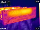
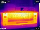
For your curiousity and as a thank you, here are a few thermal image / visible spectrum hybrid pictures showing the RX-1001 at initial power up and after being on with speaker volume set at 5.5 for about an hour. Yes...I need to do something about my cabinet as it is way too small of an enclosure, but I digress, I have little overall space to work with. I may just throw in some computer housing fans to drive down the temps and do the LCD light modification. As you can see in the photos once the unit has been powered on for some time, the LCD display is registering into the mid to upper 30C temps.
This old thread gets a bump and I don't feel my specific situation is relevant to start a new thread.
The old hifi thing is somewhat new to me and I have aquired most of my stuff via dumpster diving. Though after clicking around here and there in forums and Youtube I unfortunately fell in lust with the JVC RX-1001V. I mean 89 buttons with most of which I will never need or use? Sign me up. Watched a few auctions on eBay and local platfroms come and go for prices I was unwilling to pay, until some guy an hour drive away listed one for sale but misspelled the title so I got it faily cheap and in proper working order (as far as I know).
Yesterday I pulled the top case to reveal maybe a decade or so of dust covering everything. But, someone had been in there at one point or another but I canot tell for what. The tie wraps holding the looms together are original and none of the screws show signs of being touched with a screw driver. Maybe to do a dust cleaning too. All parts look original, even the fuses.
Being bored, I used my Flir thermal imaging camera and had a look around. There is quite the thermal gradiant in that case and componentry; a 50C spread. Maybe it is relevant to the display issue, but on the main amplifer board around ENH-071 behind the right side display are several small components that reach upwards of 90 degrees Celcius (Flir 21). That heat is soaking the board which powers and controls the right side LCD display (Flir 24 - lower part of picture). As shown in the pictures, the right LCD panel is notably hotter than the left panel (Flir 18, 19, 20 (20 - with top case off).
All was good until I carefully cleaned out the dust and reinstalled the protective cover, now my right side display is doing a flicker dance. Sometimes the display reads "PHONO" sometimes "HONO". Good times.
For your curiousity and as a thank you, here are a few thermal image / visible spectrum hybrid pictures showing the RX-1001 at initial power up and after being on with speaker volume set at 5.5 for about an hour. Yes...I need to do something about my cabinet as it is way too small of an enclosure, but I digress, I have little overall space to work with. I may just throw in some computer housing fans to drive down the temps and do the LCD light modification. As you can see in the photos once the unit has been powered on for some time, the LCD display is registering into the mid to upper 30C temps.
Attachments



Last edited: