• The move to the new server is done. There are some software and database maintenance updates in process. This has us passing the hat around to help out. We appreciate any donations. Seriously, even a dollar helps. The payment page may be found here - https://www.audiokarma.org/support.html

Kegger/blueglow kt88 project

Aikido, this is where it started and there are many more followup articles about other uses for it. I really enjoy mine which was built with a GlassWare pc board. It is a simple enough circuit to use point-to-point. I got a good deal on the pcb already assembled along with all the parts to complete the line stage. The seller also included a populated GlassWare phono preamp board and a full set of EH tubes for both. I used tested old 6SN7's in my line stage.
https://www.tubecad.com/2004/blog0011.htm

This is mine when I first fired it up. Have fun.
John
20211113_110322.jpg
 
Do you have a link to this circuit or your build details? I've been looking at the 4S preamp design as maybe a next tube project. I plan on using my Blueglow amp in my garage/shop, so it will mostly be driven by a Raspberry Pi/Boss 2 DAC running Volumio. The DAC will output 2 Volts, so I'm not sure I will really need a preamp.

I use a Pi with an Allo Piano DAC and Volumio with my Kegger amp. You won't need a preamp.
 
Do you have a link to this circuit or your build details? I've been looking at the 4S preamp design as maybe a next tube project. I plan on using my Blueglow amp in my garage/shop, so it will mostly be driven by a Raspberry Pi/Boss 2 DAC running Volumio. The DAC will output 2 Volts, so I'm not sure I will really need a preamp.

The 4S pre-amp works really well and won in my shootout over much more complex designs!
 
Do you have a link to this circuit or your build details? I've been looking at the 4S preamp design as maybe a next tube project. I plan on using my Blueglow amp in my garage/shop, so it will mostly be driven by a Raspberry Pi/Boss 2 DAC running Volumio. The DAC will output 2 Volts, so I'm not sure I will really need a preamp.

I don't have any build details posted yet on mine because it is a work in progress and I want to see how well it works as a phono preamp with my particular layout before misleading anyone. I did an intermediate test as a line preamp into the Kegger amp and it worked fine, but that is not a particularly hard test since you are dealing with levels in the 1-2V range so the gain needed is close to unity. With a phono preamp you are starting with the typical output of a turntable cartridge which for moving magnet devices is a few mV so the circuit has to provide a voltage gain at least two to three orders of magnitude larger than a line amp while simultaneously accounting for the RIAA network which has negative gain. This is where issues related to noise really come into play
 
With a phono preamp you are starting with the typical output of a turntable cartridge which for moving magnet devices is a few mV so the circuit has to provide a voltage gain at least two to three orders of magnitude larger than a line amp while simultaneously accounting for the RIAA network which has negative gain. This is where issues related to noise really come into play

This is where a highly filtered power supply and DC heaters are usually needed :)
 
Finally was able to spend some time on my Blueglow amp. I have the power supply section completed and it appears everything is ok so far. I only turned the variac up to the point I was getting about 360VDC output since the only load on it is the bleeder resistors.

I have a question regarding power cycling off to back on. I built a timer/relay module to prevent turning power back on after turning it off. Currently, I have the wait period simply the amount of time it takes for the bleeder resistors to take voltage down to zero which is a little over a minute. Is this sufficient or do we need to wait for the rectifier tube to cool down more? This is probably overkill, but after reading some of the threads on rectifier issues I thought it would be good to force myself to wait the necessary time. Besides that, why shouldn't a tube amp have some modern-day technology and I needed something to do with a spare Attiny85 chip I had laying around.....:)
IMG_1248D.JPG
 
Finally was able to spend some time on my Blueglow amp. I have the power supply section completed and it appears everything is ok so far. I only turned the variac up to the point I was getting about 360VDC output since the only load on it is the bleeder resistors.

I have a question regarding power cycling off to back on. I built a timer/relay module to prevent turning power back on after turning it off. Currently, I have the wait period simply the amount of time it takes for the bleeder resistors to take voltage down to zero which is a little over a minute. Is this sufficient or do we need to wait for the rectifier tube to cool down more? This is probably overkill, but after reading some of the threads on rectifier issues I thought it would be good to force myself to wait the necessary time. Besides that, why shouldn't a tube amp have some modern-day technology and I needed something to do with a spare Attiny85 chip I had laying around.....:)
View attachment 2613670

An alternative might be to put a thermistor in the power supply and measure the time it takes for the thermistor to recover a large percentage of it's initial (cold) resistance after the power is switched off.
 
An alternative might be to put a thermistor in the power supply
I have a thermistor in the a/c line. Here is what I programmed the module to do:
1. Back panel main switch enables a/c power to module.
2. Front panel switch(5VDC) closes main relay to send power to transformer through thermistor to power up amp..
3. After a delay of 5 seconds, thermistor bypass relay closes. This allows thermistor to cool down so it is ready for next power cycle.
4. Turning front panel switch to off opens both relays and turns off amp. Front panel switch is disabled and will not turn back on until a preset period to allow bleed resistors to bleed down high voltage on caps. I currently have this set to 90 seconds which I measured the time to get to zero volts.

Hopefully all this will prevent killing rectifier tubes, etc. Is it really necessary? No way. I did it because it was fun!

Power Control.png
 
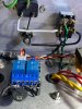
I'll have to draw the schematic. I just scribbled on a notepad. It's basically just a 5vdc supply that powers an attiny85 processor I wired up on a perfboard and a dual relay module from Amazon. Also, I will need to put some comments into the program source. I'll post it in a few days. I am heavy into wiring the remainder of the amp currently. For now I will post of the amp currently. For now I will post post some pics during testing. IMG_1249D.JPG IMG_1248D.JPG IMG_1244.JPG IMG_1243.JPEG IMG_1242.JPEG
 

Attachments

  • IMG_1241.JPEG
    IMG_1241.JPEG
    137.2 KB · Views: 44
  • IMG_1238.JPEG
    IMG_1238.JPEG
    146.7 KB · Views: 45
  • IMG_1237.JPEG
    IMG_1237.JPEG
    141.2 KB · Views: 45
nerdo, here is the schematic for the control module and wiring diagram.
Controller Schematic.png Power Control.png
BOM:
1. Hammond 229A12 transformer. I used a pc board mount one but any with around 6vac at 500ma or more should work. I used https://www.amazon.com/dp/B005T9FT12?psc=1&ref=ppx_yo2ov_dt_b_product_details
2. Any small bridge rectifier that will handle 500ma.
3. 7805 5vdc linear rectifier.
4. Two 100uf 16v electrolytic caps. Value is not very critical.
5. Atmel ATTINY85 processor chip. I was out of DIP8 chips so I used a SMD chip on an adapter board.
6. Dual 5-volt relay module from Amazon or Ebay. I used https://www.amazon.com/dp/B0728KX5KT?psc=1&ref=ppx_yo2ov_dt_b_product_details

I wired them up on a piece of perfboard and mounted that board and the relay module using nylon standoffs. You could use any small Arduino style module instead of the Attiny85. The Attiny85 will require a stand alone programmer down download to the chip whereas an Arduino can be loaded from USB. In any case, you will need either the Arduino IDE or Atmel Studio for compiling and loading the program. I don't think I can post the text source code so if anyone is interested I can email it.
 
nerdo, here is the schematic for the control module and wiring diagram.

I wired them up on a piece of perfboard and mounted that board and the relay module using nylon standoffs. You could use any small Arduino style module instead of the Attiny85. The Attiny85 will require a stand alone programmer down download to the chip whereas an Arduino can be loaded from USB. In any case, you will need either the Arduino IDE or Atmel Studio for compiling and loading the program. I don't think I can post the text source code so if anyone is interested I can email it.

Neat idea! Arduino stuff is fun to use :)
 
Does the 500 ohm KT88 cathode resistor need to be non-inductive? The only non-inductive ones I could order are 50watt instead of 10watt so they are quite large. I noticed in a close up of Mark's build I could read the part number from his and it is not the non-inductive part.
 
Also, if building ultralinear only can you leave out the 100R resistor so you have 1.2k from ultralinear tap to screen or does it need to be 1.3k total?
 
It might be neat to make up a PC board with Kicad or some other pc design software so we could have a packaged solution.
 
I'm using Kicad and EasyEDA. EasyEDA is easier if you can find the exact components like the transformer. Kicad is probably better and you can find lots of component libraries. I've had boards made from both. I may do it after I get my amp finished, but it was pretty straightforward to just wing it on a perfboard.
 
I have completed wiring my amp and fired it up gradually while checking filament voltages, high voltages, etc. Everything seems OK, but I haven't yet turned the variac up all the way to 120 VAC. I am letting it cook a while at around 90VAC to make sure all the smoke stays inside. I did input a 1 kHz signal and turned the volume knob up and saw some output sine wave into the dummy loads, so I am feeling pretty good about it so far. Can anyone tell me what the input current drawn from 120V mains should be at idle? I have a 2A slo-blo fuse and I think so far I have seen as much as 1 amp if my panel meter is accurate. I've searched this thread and haven't been able to find that yet.
 
Back
Top Bottom