• The move to the new server is done. There are some software and database maintenance updates in process. This has us passing the hat around to help out. We appreciate any donations. Seriously, even a dollar helps. The payment page may be found here - https://www.audiokarma.org/support.html

Kenwood 1100u - I'll never redo another one!

I don't doubt that you found values of the resistors high. Gosh, some equipment that I work on are 300% high. So far, I am concentrating on the paper and low value electrolytic capacitors. The FM is working but still has some capacitors that I have not checked. Even if they test good, I will probably change them since I will already have one end lifted for testing.

I might mention that even though it is proper to snip a lead and "J-Hook" the new component to the old lead (so as to not disturb tube socket lugs etc.), I strive to remove all of the old leads and install the new component the same way that the original builders did. It is just pride on my part, or maybe a challenge!

Bucking transformer is a good idea. My mains here is usually 121-122 VAC. Right now, it is being powered by a Sencore PR57 and kept at 117 VAC for testing.

Pictures later.
 
seems to depend on the type. The usual brown carbon comp jobs drift terribly. The "dogbone" type seem to be more stable unless the end cracks off then they just go open circuit.
 
seems to depend on the type. The usual brown carbon comp jobs drift terribly. The "dogbone" type seem to be more stable unless the end cracks off then they just go open circuit.

I agree. Also, storage condition, usage etc. can affect them. So far, the "dogbone" resistors have been pretty much on value, so I try very carefully to save and reuse them. The brown carbon resistors are often bridged around those small value electrolytic capacitors and I just use new manufacture 1 or 2 % 1-watt replacements. I have every value so it is a "No-Brainer" and obviously easier.

I have had good luck with this particular version in that the brown resistors, even the 10% resistors are within spec. Some 20% are close. But one 1 M ꭥ 20% was 2.2 M ꭥ !
 
yeah have run into that before. Pulled a 470k out of something that measured around 1.2M. The one right next to it measured 600k. Wouldn't be quite so annoying if they at least drifted in a consistent manner.
 
yeah have run into that before. Pulled a 470k out of something that measured around 1.2M. The one right next to it measured 600k. Wouldn't be quite so annoying if they at least drifted in a consistent manner.
I don't doubt that a bit. At least the 1% & 2% 1-watt resistors that I have are usually spot on so they will be an excellent replacement for those brown, ½-watt resistors.

I did a spot check of the 20% 1Kꭥ "swamper" coupling resistors (to the grids of the 7591). They are all over the place! They will be an easy replacement.
 
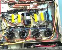
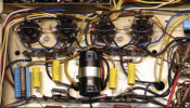
This is where we are right now. Since each capacitor replacement has made the amplifier section sound much better, I intend to continue. I tried a magnetic cartridge phono yesterday for the first time and was pleased that that part of the preamplifier was working well. I must admit that I usually work on HH Scott amplifiers and was biased (pun intended) toward the USA manufactured vacuum tube audio equipment when I was growing up, a long, long time ago. But this receiver sounds great so far. It will be one of my "Keepers", along with the Sansui 1000A.

Progress so far:

IMG_7010.jpg
 
If anyone wants a close-up photo of any part of this chassis, send me a PM. I took this picture with a Canon digital and "dummied it down" for the internet. I have the original of course.
 
Pretty much finished now and playing well. The only things still now working well are the AM portion of the tuning capacitor is scratchy at a certain location. Exercising it has helped as well as DeOXIT on the connections between the stator and rotor. FM Stereo could use a touch-up but I am leaving that alone now. It was obvious that the phono input had been used most of the time. The indicator lamp was open. I "borrowed" the lamp from the Tape Head location on my donor set.

One confession here... Usually, with something as complicated as this receiver, I work slowly, replacing 2 or 3 capacitors as I go, test again and make sure it still works and is getting better. After working on the AM part of the tuner, it still worked fine. Then, when working on the next section, on power up, no AM and smoke rising from a resistor. What the heck? I took a break and went back after an hour. Since it was a B+ resistor to one of the IF transformers, I was really worried that I may have also smoked a transformer. But I found that I had mashed a lead from a component on an adjacent tube against a tube lug that was supplied by that resistor. Resistor replaced, another careful inspection and it works.

Still todo is cleaning up the chassis, resolve the AM tuning capacitor noise, and an intermittent Tape Monitor switch. This thing is a beast! It weighs 42 pounds and my back knows that every morning. But it sure does have good 1966 sound emanating from those Hitachi 7591 tubes through large output transformers.
 
I used the KW1100u as my shop amp and it's on almost every day. One cool thing is that it does not power the FM section unless it is selected -- that may be true for the AM as well, but I haven't stopped to look. It sounds really good through some Dynamo 25 speakers.

I have some extra parts if you need them . . . bulbs and switches for starters. Not sure I have a spare tuning cap for the AM and if I once had some IF cans I gave them away.
 
Update several months later. This receiver is still on the bench. Why? Well, because it is playing so well and I absolutely love listening to it. It has been stable and every time I turn it on, it just plays... with one exception. I was heartbroken one day when the right channel was totally out. I started to trouble shoot and finally tracked it down to the....... Tape Monitor switch. It had been cleaned but was still wonky. It is too complicated to replace and what makes it work is to just exercise it gently. I will have to live with that "problem".

As for the AM, the tuning capacitor finally settled down and I no longer have problems in that certain part of the dial.

Magnetic cartridge inputs work well, as do all of the inputs. These are complicated but wonderful receivers. My recollection is that they were a one year only model. Mine has all Japanese tubes, Hitachi, Matsushita and Toshiba. As I said earlier, this one is a keeper. Unfortunately, the other 1100u that I had was in poor condition. I parted it out and kept the most important parts (including the tuning capacitor!!!).

Thanks for taking the time to read this.
 
Update several months later. This receiver is still on the bench. Why? Well, because it is playing so well and I absolutely love listening to it. It has been stable and every time I turn it on, it just plays... with one exception. I was heartbroken one day when the right channel was totally out. I started to trouble shoot and finally tracked it down to the....... Tape Monitor switch. It had been cleaned but was still wonky. It is too complicated to replace and what makes it work is to just exercise it gently. I will have to live with that "problem".

As for the AM, the tuning capacitor finally settled down and I no longer have problems in that certain part of the dial.

Magnetic cartridge inputs work well, as do all of the inputs. These are complicated but wonderful receivers. My recollection is that they were a one year only model. Mine has all Japanese tubes, Hitachi, Matsushita and Toshiba. As I said earlier, this one is a keeper. Unfortunately, the other 1100u that I had was in poor condition. I parted it out and kept the most important parts (including the tuning capacitor!!!).

Thanks for taking the time to read this.

I just lucked into this thread because of your new post. Good read, and couldn't agree more; "complicated but wonderful" describes them perfectly. I have a couple in the to-do pile myself (Lafayette & KW) so when I have the time (and a better camera) I'll post the results. They really sound lovely, and when the tuners are properly aligned, wow!

The Japanese receivers are extremely difficult to work on, and you really need to be very patient and careful, 'cause it's super easy to damage things if you get heavy handed.
I can certainly understand and respect the effort required, as I grew up repairing German radios. You and Buzz certainly seem to have the necessary chops to work on these:)
 
I just lucked into this thread because of your new post. Good read, and couldn't agree more; "complicated but wonderful" describes them perfectly. I have a couple in the to-do pile myself (Lafayette & KW) so when I have the time (and a better camera) I'll post the results. They really sound lovely, and when the tuners are properly aligned, wow!

The Japanese receivers are extremely difficult to work on, and you really need to be very patient and careful, 'cause it's super easy to damage things if you get heavy handed.
I can certainly understand and respect the effort required, as I grew up repairing German radios. You and Buzz certainly seem to have the necessary chops to work on these:)
To say that Japanese receivers are difficult to work on is an understatement of course. But when you say that you need to be patient and careful is spot on. The terminals are a lot thinner and flimsy. I am one of those who insists on removing all of the old component lead rather than "J" hook splices. That is not to say they are wrong, they certainly make sense and can cause a lot less collateral damage to the area one is working on. But it gives me great satisfaction to accomplish this. And from above the chassis... no one would ever know... except me.
 
Kenwood kw-1100u

HI YA..
I am also working on one of these old Recievers.. this would be my first all tube stereo to restore..for sure it is packed with Capacitors..I have ordered all Caps already..and tested and tested the tubes.. output tubes seem fine, all of the 6BN8's are weak.. interesting thing is this does work (without output tubes in) , and picks up FM Really nice and in stereo.. Stereo indicator light is very dim.. least of my worries yet..but as you can see from pics i think a few things in the power supply have been replaced already..2 large wirewound resistors i have been trying to figure out as the diagram only give the wattage.. R4015.. ( i think it is R401 in reality).., it's the large ceramic white wirewound and I think it's a 5 ohm 10 watt wirewound but hard to say as the lettering is all burned off and in the Diagram the designation numbers are so close together, and the other is the green one that someone stuck in, which is R 402.. I think it's a 470 ohm wirewound..look at pics and you will see..can anyone give me a proper Value of these..?
if you see anything that does not look factory before I begin please let me know as the manual is hard to read...(poor copy)
thanks!!
I know this an old thread, but my 1100u just stopped working and I think it’s because the solder from one the wires that run straight across the power tubes connecting them. I can at least solder so maybe I can just re-attach it and things will be OK. My question is what is the gauge and kind of wire that’s running straight across the power tubes?
 
I know this an old thread, but my 1100u just stopped working and I think it’s because the solder from one the wires that run straight across the power tubes connecting them. I can at least solder so maybe I can just re-attach it and things will be OK. My question is what is the gauge and kind of wire that’s running straight across the power tubes?
There is very little current on that wire. 22 AWG or 20 AWG should be fine.
 
There is very little current on that wire. 22 AWG or 20 AWG should be fine.
Can that go all the way across the power tubes? I just wonder because it seems there is a lesser watt wire running in between some. Thanks for your response. This is a beats to deal with.
 
I assume that the wire you are talking about provides voltage to the screen grids. I can't visualize how it might have become unsoldered. A best practice is to add 100 ohm 1/4W resistors on EACH tube, to prevent damage to the output transformers in the case of a tube failure.

Without meaning to offend, troubleshooting this problem may require service by someone familiar with tubes and receivers.
 

Attachments

  • KW1100 output tubes.jpeg
    KW1100 output tubes.jpeg
    252.1 KB · Views: 27
I assume that the wire you are talking about provides voltage to the screen grids. I can't visualize how it might have become unsoldered. A best practice is to add 100 ohm 1/4W resistors on EACH tube, to prevent damage to the output transformers in the case of a tube failure.

Without meaning to offend, troubleshooting this problem may require service by someone familiar with tubes and receivers.
Here is an example of what I'm talking about. This isn't my receiver (it's one I found on the internet), but mine is wired similarly. Do you see how it looks like 20AWG solid core wire that goes across the bottom of the tube socket. Then, in between each socket connecting the tubes, it looks like there is like 12AWG stranded wire. Why would you do this? Could you just use 20 AWG solid core all the way across?
 

Attachments

  • Kenwood 1100u tube sockets.png
    Kenwood 1100u tube sockets.png
    786.7 KB · Views: 14
I don't see why you couldn't use 20 gauge wire -- there is maybe 20mA of screen grid current split among the four tubes. Maybe they used bigger gauge to provide a kind of "bus". I don't know.
 
There is so little current on this circuit that you could use even 26 AWG etc. My guess is that the heavier wire was used because it was available as buss wire and/or it was easier to work with.

Just an update, I am still using the receiver as my bench audio. The only issue is some scratchy pots and the Tape Monitor switch. That continues to be problematic. Eventually, I will have to do some kind of surgery. But the rest of it sings along with vintage Japanese tubes.
 
Back
Top Bottom