• Please note that Audiokarma will be offline briefly for updates early on Monday morning, September 28th.

Kenwood 1100u - I'll never redo another one!

I have had two of them. One I restored and it sits on the bench as a test amplifier. (The other one was parted out because of severe cosmetic damage). It is a very good receiver. Even though I am downsizing, I would spend that kind of money in a second. It came with Hitachi 7591 output tubes.

Here are some before and after photos for reference. (A few more parts may have been replaced after the "After" photo) If you have any questions, don't hesitate to ask.

Ah, the familiar flat grey of Elna capacitors! Thanks much for the reply and for sharing those photographs; I will almost certainly reach out with questions. I'm sure to have a handful. I just hope there's nothing busted in this unit that is made of unobtainium...

That unit in the photographs sure is clean. Is that your bench amp?
 
Ah, the familiar flat grey of Elna capacitors! Thanks much for the reply and for sharing those photographs; I will almost certainly reach out with questions. I'm sure to have a handful. I just hope there's nothing busted in this unit that is made of unobtainium...

That unit in the photographs sure is clean. Is that your bench amp?
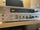
Indeed, that is my bench amp connected to two Bang & Olufsen S-75 speakers on the top shelf. This receiver is quite a performer, great frequency response and is working those 7591 output tubes well.

In the photo of the completed receiver, there are still shown a few gray capacitors. Those were also replaced. And as mentioned above, Elna gray capacitors (that look like electrolytic) are paper. They are almost always leaky.
 
Indeed, that is my bench amp connected to two Bang & Olufsen S-75 speakers on the top shelf. This receiver is quite a performer, great frequency response and is working those 7591 output tubes well.

In the photo of the completed receiver, there are still shown a few gray capacitors. Those were also replaced. And as mentioned above, Elna gray capacitors (that look like electrolytic) are paper. They are almost always leaky.
Thanks for the info, I didn't realize that the larger caps in the 1100u were paper (!) caps. They'll be super leaky then, instant no-confidence vote.

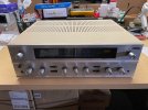
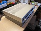
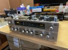
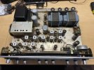
In other news, I took the plunge:
 

Attachments

  • IMG_8195.jpeg
    IMG_8195.jpeg
    85.2 KB · Views: 25
  • IMG_8191.jpeg
    IMG_8191.jpeg
    116.2 KB · Views: 22
  • IMG_8192.jpeg
    IMG_8192.jpeg
    116 KB · Views: 19
  • IMG_8194.jpeg
    IMG_8194.jpeg
    122.3 KB · Views: 19
  • IMG_8193.jpeg
    IMG_8193.jpeg
    139 KB · Views: 26
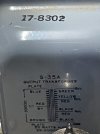
First thing I've noticed is the ouput transformers have been changed. These in here are made in the USA and a different make/model than what would have originally been installed:
 

Attachments

  • IMG_8198.jpeg
    IMG_8198.jpeg
    83.3 KB · Views: 15
  • IMG_8197.jpeg
    IMG_8197.jpeg
    122.2 KB · Views: 15
No guarantee that they are appropriate for your unit, though. I think 5K primary may be a bit low.
 
yeah 5K for a 7591 isn't really where I'd expect. You could go the other way, 8 ohm load on the 4 ohm tap to make it a 10K primary. Screen voltage would want to be lowered to make it happy but the late Fisher 400 ran 7868 tubes (same thing, different base) with 10K transformers. They didn't do a great job matching the screen voltages, but there is a thread on here from @dcgillespie how to fix that with EFB providing a more appropriate screen voltage.
 
A pair of 6L6GC in class AB1 push-pull at 450-475V B+ into a 5kΩ P-P load is about the same operating point used in a lot of vintage Fender-style designs.

At this voltage/impedance, a well-biased 6L6GC pair will deliver somewhere in the 20-25W range in class AB1.

The original Kenwood 1100u spec is 37 watts per channel into 8Ω in stereo mode, so the 20W power limitation of the Triad iron is holding you back. Also the schematic shows a B+ of 490 with 115VAC in, so if your line voltage is 123 you might be looking at a B+ of 524V!

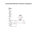
I highly recommend a "bucking" style transformer to supply 115V to the unit. It will run a lot cooler and the filament voltage won't be higher than it should be.

If you can find a pair of OPTs from a Sansui 1000A they are drop-in replacements for the Kenwood iron and you won't have to redesign the output circuit.

(I turned a KW-1100u without any of the original iron into an AM/FM Preamp like the McIntosh MX110z . It was a complete PITA to do but it works . . . )
 
Last edited:
Thanks for the feedback and input, @arts @BuzzK @gadget73 @kvflyer :rockon:

Agreed, 5k is low; I don't have a manual for the 1100u (yet) so I can only look at the output tube stats. Considering where 7591s like to sit, this should be more like 6600 on the primary. That'll be something I want to correct for sure.

Has anyone worked with these output trannys before? They'd have an additional secondary that I don't need, but that doesn't matter much to me:


Edit: Fixed wonky URL
 
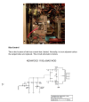
Here are some bits, showing modification of the fixed bias circuit and the bucking transformer located on the chassis.
 

Attachments

  • Screenshot 2026-09-13 at 2.08.53 PM.png
    Screenshot 2026-09-13 at 2.08.53 PM.png
    381 KB · Views: 12
  • IMG_8317.jpeg
    IMG_8317.jpeg
    311.5 KB · Views: 12
  • Screenshot 2026-09-13 at 2.15.26 PM.png
    Screenshot 2026-09-13 at 2.15.26 PM.png
    54 KB · Views: 12
Here are some bits, showing modification of the fixed bias circuit and the bucking transformer located on the chassis.
Nice, that's a clean implementation, too. Thanks for the suggestion, that's a good one -- I've even considered an AmpRX BrownBox between this receiver and my mains. Decisions, decisions...

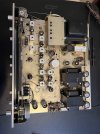
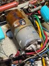
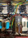
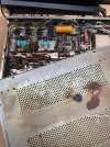
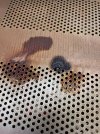
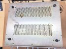
So some updates, took a break from the regular paying job to crack the bottom off of this beast. Right away I noticed before even opening it, on the bottom, evidence of leaking electrolyte and knew that we had a winner winner chicken dinner ... evidenced by these various photos ... This big ol' pukey, leaky rascal connects to pin 5 of an output tube.

edit: typos
 

Attachments

  • IMG_8208.jpeg
    IMG_8208.jpeg
    149.6 KB · Views: 19
  • IMG_8206.jpeg
    IMG_8206.jpeg
    154.9 KB · Views: 15
  • IMG_8205.jpeg
    IMG_8205.jpeg
    167.4 KB · Views: 14
  • IMG_8204.jpeg
    IMG_8204.jpeg
    199.4 KB · Views: 14
  • IMG_8203.jpeg
    IMG_8203.jpeg
    213.1 KB · Views: 18
  • IMG_8202.jpeg
    IMG_8202.jpeg
    155.7 KB · Views: 18
:rflmao:
For sure, 'tis but a scratch lol

Yessir, that'll buff right out:biggrin:

Edit; re the transformers, I wouldn't worry too much about replacing them. Get the machine up and running first, and see how it performs. Unless you are aiming for perfection, I'm betting they'll be fine for everyday use at reasonable volumes.
 
Yessir, that'll buff right out:biggrin:

Edit; re the transformers, I wouldn't worry too much about replacing them. Get the machine up and running first, and see how it performs. Unless you are aiming for perfection, I'm betting they'll be fine for everyday use at reasonable volumes.
Yep, the plan is getting this working, even if just minimally, and then do a full recap, change out problematic resistors and such. I would eventually like to find a better pair of matching OPTs for this. A pair of Sansui 1000A OPTs was recommended in this thread, and for the right price they can be had... :thumbsup:
 
if you do that, the Triads could be re-purposed for something else. 5K and 25 watts is perfect for a 6L6 class A push-pull amp

1789480987552.png
 
if you do that, the Triads could be re-purposed for something else. 5K and 25 watts is perfect for a 6L6 class A push-pull amp

View attachment 3837085
That's the plan, to eventually use these in another project, one which they're better suited at performing in. Cheers for the info! :)

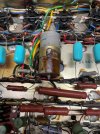
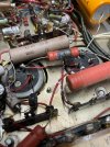
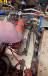
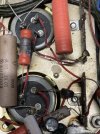
Recurring theme: I took another long break from the paying job and was gazing into the receiver, playing "Onesy, twosey, what does that thing even do-sey?" ... when I realized the large resistor that is wired between the two filter capacitors is smoked. Completely crispy, black in the middle. What's even more interesting is the even larger resistor right next to it. Wow, kaboom, cracked right in half! There are also some rather thin red wires that come directly off of the main filter cap lugs and go to various nodes -- you can see in an image that those are proper BBQ'ed, insulation clean burned off of them in places. Whatever happened, massive juice and massive heat was the result. :(
 

Attachments

  • IMG_8218.jpeg
    IMG_8218.jpeg
    160 KB · Views: 8
  • Screenshot 2026-09-15 163221.png
    Screenshot 2026-09-15 163221.png
    955.7 KB · Views: 8
  • IMG_8219.jpeg
    IMG_8219.jpeg
    163.2 KB · Views: 8
roasted resistors on caps like that usually indicate a short, often in the cap itself. Honestly the resistors being right there is not ideal for the cap. Some amount of heat dumps down the leads right into the cap body which makes them age more. Also just the heat in the chassis right underneath warms them and that doesn't help either.
 
Back
Top Bottom