• The move to the new server is done. There are some software and database maintenance updates in process. This has us passing the hat around to help out. We appreciate any donations. Seriously, even a dollar helps. The payment page may be found here - https://www.audiokarma.org/support.html

Kenwood 700M restoration

gonzothegreat

Super Member
After reading the sticky thread on DC offset, a little voice in my head said I should keep on the lookout for one. I figured I'd never find a BA-5000 in my price range but a 700M might not be out of the question.

I finally found one but jeez, she was in sorry shape. I decided to take up the challenge after EW told me these amps are relatively simple to fix. He sent me the schems on Cd that he spent untold hours cleaning up in Photoshop. Thanks EW!

So how bad was she butchered? Well, she was missing the shielding cages for one driver board and the protection board. Most of the front panel buttons didn't latch except for the power switch. Half-assed wire mods of an unknown nature. Blown outputs and roasted driver board resistors in one channel were the obvious problems. The amp had been worked on (I would say *over*) previously for the same problems in the other channel (using generic NTE style semis). He might have also been responsible for the wire mods but I couldn't tell. There were also two broken AC outlets on the back panel. Lots of chassis oxidation, tons of missing screws and a bent bottom plate rounded out the damage to this once-fine lady.
 

Attachments

  • 1091181151997_1089065754175_07_20__Kenwood__2.jpg
    1091181151997_1089065754175_07_20__Kenwood__2.jpg
    41.1 KB · Views: 247
Last edited:
Register to hide this ad
Faceplate cleaning & repair

Since cleaning the faceplate would give me something nice to look at while working on the other parts, I decided to start there.

Here it is after I removed it. This is one hefty faceplate. Note the tape residue and other gunk.
 

Attachments

  • 700m-1.jpg
    700m-1.jpg
    30.1 KB · Views: 179
Last edited:
Now here is the same faceplate after some Flitz (think of it as Simichrome-lite) metal polish and a generous dose of Windex.
 

Attachments

  • 700m-2.jpg
    700m-2.jpg
    29.1 KB · Views: 199
Last edited:
Now for the flipside

EW said my sticky buttons were probably due to a misaligned faceplate or button spacers. Turned out the glue (looks like the same evil conductive corrosive gunk that they used to secure components to the PCB with) holding the button spacers had failed and they were dangling around the neck of the buttons thereby preventing them from latching.

Here is a shot of them sitting loose on the clean front panel. Notice the dried glue rings around the button holes.
 

Attachments

  • 700m-3.jpg
    700m-3.jpg
    30.6 KB · Views: 156
Last edited:
Once cleaned with some Windex, they were glued in place with a few drops of superglue. Here's the photo...

The switches worked perfectly after I reassembled the front.

The next step will be to repair the broken outlets and undo the ugly wiring mods.
 

Attachments

  • 700m-4.jpg
    700m-4.jpg
    28.7 KB · Views: 101
Last edited:
Tip: Don't use superglue when something of lesser strength will do the job. Most of the 700M's have those plastic 'thingies' for the switches removed anyway because they cause problems.

I'd have used a small dab of silicone, in case they needed to be removed.

BTW...sorry I didn't email you back about the prints...DAMN they look good!! Nice to have a printer that'll do that size. Excellent work, I'm tempted to have one of 'em framed. ;)
 
Schematic printing tips for the masses

I would have prefered to use a glue like what Kenwood used but it was 3am and I had a severe burr up my ass that I wanted to fix the faceplate once and for all. I couldn't find my caulk or my hot melt glue so the 99 cent crazy glue stepped up to the (face) plate. I was a little worried that I wouldn't get the alignment right the first time but I rolled the dice and I nailed it. Whew!

Here's a little tip about making usable schematics from JPG/TIFF scans. I have a large format printer (11 by 17) for stuff like this but in some cases, ledger just doesn't cut it. Factory schems are often 24 by 36 or larger. Since printing out something this big at Kinkos might as well be printed on gold leaf, here's my solution. I use a feature of the HP printer driver that tiles the printout across a matrix of pages (be sure to turn on borders until you get the hang of cropping the pages). There are programs that do the same for any printer (I used to use something called Poster 7) but those cost money. I then assemble the matrix at Kinkos using their rotary paper cutter to get a nice straight edge. Another hint - always make at least two copies so you can make all your mistakes on the first one. Tape them together and then use the large format copier to xerox the matrix of sheets onto one large sheet. Cost less than $5 at my local Kinky's. Ta-da! You have an engineering size print that you can take notes on and not go blind. Be sure to save the original taped up copy for future use if you don't want to repeat the cutting & taping (the only real hard part of this method)

I just figured out that a strange wiring mod from the protection board is just a bypass of the speaker selector switch. Still have to figure out if a jumper wire on the protection board is factory or not. There is an empty two pin header pad that looks like somebody pulled the pins because there is glue residue just below the three pin header that goes out to the speaker selector switch.

I don't plan on working on her again until next week so this thread will be quiet for a bit.
 
The more I dig into this amp, the more I think it should have been a parts unit except that I'm too crazy to part it out. It looks like it was stored in somebody's leaky shed for a decade. Most of the gunk cleaned off easily but the chassis has some corrosion issues. Every ground that attaches to the chassis will be burnished and deoxided. Might have to put new spades on them too. Hopefully the big power supply cap that looks like it got wet inside the plastic is OK.

I pulled the driver boards and rebuilt them with the exception of the input diff pair since I couldn't find my DMM with the beta test. Removed all traces of capacitor glue gunk and acetoned off a thick layer of ancient flux from the solder side. I'm pretty sure it was factory flux. I also noticed a crack in one driver board. It didn't affect any traces so I wasn't worried.

As EW warned me, all the connectors had a layer of oxidation on the silver pins. He suggested Brasso but I used something called "Tarn-X" instead. I washed the tarn-X off and applied some Pro-Gold to the pins and plugs.

I undid the hack-mod to bypass the speaker select switch. Fortunately they clipped the wires close to the terminals so I didn't have splice in an extension.

On the back panel, I bypassed one of the broken outlets when I realized one of the replacements was too small. I will probably leave the other broken one until I get the amp running.

This amp has a soft-start circuit that goes through a large power resistor. Trouble is the resistor fries if an output dies. I replaced it with a 25w 8 ohm unit. Wanted to use a nice metal finned unit but Digikey was out.

Replaced the outputs with On-Semi devices. I had to pull the heatsinks from the chassis because the connectors to the driver boards were oxidized (Tarn-X to the rescue again). This was a pain as it involved removing the front and rear panel (and nearly forty screws!). I discovered heatsink grease is easily removed with pre-moistened glass-cleaner wipes. It works a lot faster than acetone soaked Qtips.

The relay board should have been simple but it didn't work out that way. I cleaned the oxidation off the pins and when I was rinsing the tarn-x off, water got inside all the relays. Arrggh! I had to remove all three relays, pop the covers and dry them out. While I was in there, I hit the contacts with some cleaner just so I never have to touch them again.

The shields for one driver board and the relay board are missing. I was told that I should find someplace that works with sheetmetal like a furnace & heating company and they would be able to fab a copy of the driver shield. The relay board is going to be trickier.

To be continued...
 
Last edited:
Here are pics of the driver board before and after the mods suggested by EW.

Here are the mods for the later style driver board (as I have)

Ce1 - Change to 1.5µf 250V Panasonic ECWF(B) metal polypropylene,
Digikey #PF2155-ND
Ce5 - Change to 330µf 25V Panasonic FM type, #P12386-ND
Ce6 - Change to 150µf 50V Panasonic FC type, #P11256-ND
Ce11 - Change to 470µf 10V Panasonic FM type, #P12361-ND
Ce12 - Change to 220µf 100V Panasonic FC type, #P10780-ND
Ce14 - Change to 330µf 25V Panasonic FM type, #P12386-ND
Ce17 - Change to 330µf 10V Panasonic FC type, #P11184-ND
Ce18 & Ce19 - Change to 47µf 10V Panasonic FC type, #P11180-ND
 

Attachments

  • 700m-5.jpg
    700m-5.jpg
    117.3 KB · Views: 308
  • 700m-6.jpg
    700m-6.jpg
    119.3 KB · Views: 291
Last edited:
This is a shot of the relay board after I had to open and clean all three relays. I wasn't sure what to make of the empty two pin header in the middle top of the board. The back of the board had a single diode mod and a jumper. According to EW, these were to immediately open the relay upon power down.
 

Attachments

  • 700m-7.jpg
    700m-7.jpg
    135.4 KB · Views: 204
Last edited:
Appears that you have a newer style relay board...is your amp a multivoltage model with the big switch for voltage selection on the rear?

The 'mod' I spoke of with a diode and capacitor usually is mounted just above the left power meter at the front of the unit, with a single wire that runs to the relay board. This is usually done on the older boards, not the newer ones. I'd suggest whipping out the prints and seeing where they connected the diode. Maybe it's needed, maybe not.

Driver boards look good...

As far as being a 'parts unit'...naaa.. I've got a parts unit Extrodenaire. :yikes:
 
Final check and smoke test...****!

Its been about a month since I've touched this amp. I hauled her downstairs and noticed immediately that the pins on the driver boards had oxidized again even though I ProGolded them. I gave up and went over every pin on the driver boards and output assembly with a toothbrush size wire brush. Much better.

I disassembled each channel (one at a time) and made sure I hooked everything up right. I even found a tarnished connector coming off one of the low current PS cap boards that I had missed every other time I ripped her apart.

I pulled off the back panel and double-checked all my work there. Lugs on 22000uF 80V caps - clean and continuity down to the diode pack. Soft start resistor appears to be well insulated and good to go.

Getting excited now. Dug up my lightbulb jig and found a 100w bulb. Plugged everything in and hit the power switch.

Lightbulb, lightbulb
burning so bright
something is shorted
this sucks, alright...

I rarely venture into prose and this is a perfect example why...

Dammit! I replaced every output, double checked all semis, upgraded every driver board lytic and ditched all the cheap Radio Shack resistors the last tech used.

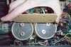
My gut thought the big caps might be trouble but I didn't want to think of dropping another $100 on parts. I pulled the cap PCB off and here's what I saw.
 

Attachments

  • 700m-8.jpg
    700m-8.jpg
    92.8 KB · Views: 272
Last edited:
Since I've never seen a huge cap like this that has vented, I could be wrong but my spider sense says these two 22000uF 80v beasts have passed their gas and let out the magic smoke. Where's my cap checker? I haven't taken any voltages off the transformer but I hope to the vintage audio gods the transformer wasn't whacked by whatever took the twins out.

I'll also have to pull the relay board (again) so I can check the diode/jumper mod. The two pin header still has me puzzled as to what it could have been. This 700m doesn't have the voltage switch.

If nothing else, I'm eternally thankfull I used my lightbulb jig.
 
Last edited:
Those have vented. Perhaps we know the origins of the 'mystery liquid' in the clear cap covers now.

You can get the caps replaced for less than $60. Interested?

I built a Class D amplifier back in the early 80's as my grad project. It was cannibalized years ago. However, I have been hanging onto a Sprague 36DX 25,000µf 75V computer-grade cap for years...charging and discharging it from time to time to make sure it stays healthy. Yep, it's 20 years old. But it looks like new (if that matters...) and performs like new. What's more, it's 3" x 4.125", just like the originals in the 700M.

Problem is, I had built a single-ended supply, and this cap never had a mate. After seeing your post, I decided to find one...here ya go:

http://www.surplussales.com/Capacitors/Electrolytics/10000uF-300000uF.html

There is a 25,000µf 75V Sprague 36DX cap on that page for $35 (a little high for a 'surplus' place, but these caps are rare). These were the best in the biz when they were made (Vishay bought the Co. in the 90's and the product line has been considerably changed) and this should be a mate to the one I have. Mine does not have the tall terminals that the stock ones do on the 700M (and the one on the web page probably doesn't either), but screw it...use a spacer or a few washers if you need to. Also, the 75V rating is fine, as the actual supply voltage to the output stage is only about 67V or so.

By far the cheapest way to go.

If you powered on with the light bulb, no way did anything fry (as long as the bulb was 100W or smaller). Also consider that if the bias is for some reason cranked way the hell up it will draw enough current to brightly light a bulb even though nothing is blown.

I'd suggest removing the drivers boards and disconnecting the connectors to the power devices and then powering it up. That will give you a clue as to the origin of the shorted component (if it is somewhere other than the vented caps) and let you see if at least the supply voltages are in the ballpark.

You can also power up with the driver boards in and the output transistors disconnected to see if anything on the driver boards is shorted, BUT, you notice that one of the thermal diodes is on the heatsink with the output devices. This diode MUST be connected or else Q9 sees the full supply voltage on its base and fully turns on, letting the magic smoke out of the resistors in and around the output stages of the driver board. This means leaving the one connector that runs out to the STV-3H diode and back connected while the rest of the connectors to the output devices are off.

I'm suprised that you didn't replace the stock POS bias pot. Still, make sure that it is set to a small value (75 ohms or so) until you have a chance to set the bias.

You don't want to hear this, but this is a very simple amp and about the easiest to work on that I know of. Hang in there. :thmbsp:

Edit: Went back and re-measured the original 700M caps. They are 3" x 4.5". The Sprague caps I'm recommending as replacements are then about 3/8" shorter than the originals. It won't be an issue.
 
Last edited:
I'd be willing to bet the driver boards and outputs are just fine. I didn't replace the bias pots because I wanted to leave that until after I got it on its feet. The pots are sitting in the digikey box along with the inputs you suggested. I was going to have to pull the driver boards at that point to replace the input diff pair (now that I found my DMM with beta check).

When I powered up the amp, I saw the bulb light up at full brightness so I turned it off after 5 secs. Nothing flaming or smoking. I powered it up a second time and counted slowly to ten. No relay action.

Thanks for the legwork on the caps. Will try to dig around in the amp tonight. Will PM you for details on purchasing the orphan cap later tonight.
 
Last edited:
OK...you know the drill...disconnect and remove the driver boards, and disconnect the output devices. Then power up again and see what the bulb does.

Glad I saved this cap all these years...I'd be nice to know that it can serve duty in a 700M. Basically it's yours for $10 plus whatever it takes to ship it. I wish the one at the surplus place was cheaper, but still, for what you're getting it's not too bad a deal. To replace two big computer-grade caps for that price is a damn nice deal.

Melodrama? Try doing this all the damn time. I have many moments of cold sweat and cursing. Apologies are not warranted...
 
He's got the replacement cap from Nebraska Surplus, but I just sent him my cap yesterday. Prolly be a few days till they get installed. :yes:
 
Someday my caps will come...

Once I get the cap EW sent me, I'll still have to screw around with the cap mounting hardware. The original terminals on the caps were big ass screws while the ones on the new caps are considerably smaller. Will have to replace the screws with longer ones, add some washers and probably redo some other hardware that looks marginal due to corrosion.

Since I'm currently carless, I'll have to thumb a ride to the hardware store on the weekend.

I shouldn't have to wait too long as the schems he sent me when I started all this arrived in under a week. Should have the cap before the weekend.

After it passes the smoke test, I will still need to fab new shields for the driver & relay boards (not to mention replacing the skanky original bias pots and ancient diff inputs). Will bypass the filter caps too.

Speaking of the diffs, the devices used on my late model driver boards don't match the schems. They aren't 2SA620. Don't have my notes in front of me but they were in packages similar to the 2SC1452s. I'm sure it was factory since it was done on both channels and the work quality obviously wasn't the half-drunk tech school dropout who used the NTE devices.
 
Last edited:
Back
Top Bottom