• The move to the new server is done. There are some software and database maintenance updates in process. This has us passing the hat around to help out. We appreciate any donations. Seriously, even a dollar helps. The payment page may be found here - https://www.audiokarma.org/support.html

Kenwood 700M restoration

Well, the shields can wait till it's running. Cosmetic mostly.

Wish I had known about the input trannies. Once you have it going, check offset. If it isn't that great, I'd be more than happy to match a couple of pairs of Zetex ZTX795A's to pop in it.

What's with the car? :confused:
 
Quick question about the driver boards, when you replaced the caps, did you use the same values that were on it or did you increase the values?
 
gonzothegreat said:
Here are pics of the driver board before and after the mods suggested by EW.

Here are the mods for the later style driver board (as I have)

Ce1 - Change to 1.5µf 250V Panasonic ECWF(B) metal polypropylene,
Digikey #PF2155-ND
Ce5 - Change to 330µf 25V Panasonic FM type, #P12386-ND
Ce6 - Change to 150µf 50V Panasonic FC type, #P11256-ND
Ce11 - Change to 470µf 10V Panasonic FM type, #P12361-ND
Ce12 - Change to 220µf 100V Panasonic FC type, #P10780-ND
Ce14 - Change to 330µf 25V Panasonic FM type, #P12386-ND
Ce17 - Change to 330µf 10V Panasonic FC type, #P11184-ND
Ce18 & Ce19 - Change to 47µf 10V Panasonic FC type, #P11180-ND
All listed. ;)

These are for the NEW style driver boards, BTW. The old boards have different component designations, I think.
 
EchoWars said:
Well, the shields can wait till it's running. Cosmetic mostly.

Wish I had known about the input trannies. Once you have it going, check offset. If it isn't that great, I'd be more than happy to match a couple of pairs of Zetex ZTX795A's to pop in it.

What's with the car? :confused:

I have ten Zetex devices waiting to be matched. I should be able to find two pairs out of the batch that will get us in the ballpark on offset.

EW's cap came today. The mounting posts are a millimeter or two shorter than mine. His has a 1980 date code while mine is from '97. Other than the minor physical differences, they're twins. I had to do some errands so I got a lift to the hardware store to get longer screws and a bunch of washers (all stainless steel). I found some hex head 10-32 5/8" that are hopefully long enough.

Regarding the car, it was a '93 Merc Tracer wagon that I just had an in chassis overhaul done on back in Feb. They also did a tranny tune up and said it was in great shape. In October it started having trouble shifting. Brought it in and they said it would cost $2000 to fix but they didn't suggest it. The Mazda tranny was a bad design poorly executed. People have tried various fixes to make it reliable to no avail. Now she's being picked over for parts at the local junkyard.
 
Last edited:
Sucks about the car...damn!

Yeah, the cap is old, but I've babied it through the years charging and discharging it from time to time, expecting to eventually use it in something. Just never happened.

So, Nebraska Surplus has the tall post cap... Hard to tell from the pic you sent, but the difference isn't much. If the age or the post length is an issue for you, I'll take the cap back, no problem. Just let me know.
 
Just pulled the driver boards and disconnected the bad caps. Powered it up and the voltages looked OK. 47vdc at each point where the caps would be had I left them in the circuit. 47vac for each winding off the trannie. Next step is to install the new caps and put the driver boards back in.

I took some pics of the mods on the relay board. The foil side shot shows a jumper from post 22 to 30 and a diode tacked in as well. It looks like there was a header just off D11 since there is glue residue near the holes. Nothing there now. Solder is nicely reflowed on the pads for the now-absent header. The mods on the trace side of the relay board sure look factory. Same kind of wire as used on the front of the PCB for the labeled factory mods on this new style board and the diode has shrink tubed leads. No chance the last greasy techie would have bothered with protecting the leads.

The input diff trannies used on my driver boards are 2SA810. Don't know how these compare with the 2SA620. Probably nowhere as good as the Zetex devices. I just gain-matched three pair within five points out of a batch of ten so I'm ready to drop them in once she's running.

EW - the difference on the terminal height was a millimeter or two. Nothing serious. I just mentioned it for the sake of detail. Same for the date codes. Don't worry about refunds - I'm satisfied.

Stay tuned!
 
Last edited:
Detail shots of the relay board

Just documenting the relay board mods for the record.
 

Attachments

  • 700m-9.jpg
    700m-9.jpg
    95.1 KB · Views: 141
Last edited:
After I double-checked the voltages on the 65 volt supply, it was time to drop in the new caps. I can't be sure but it seems like the corrosion was heaviest around the vented caps. Nothing too serious but some icky stuff that I wouldn't want in my lungs.

Pulled the old caps (after marking polarity on the pcb and taking pics) and dropped the new ones in place. Added some stainless steel washers below the pcb to raise the board a bit. Plugged it into the lightbulb jig and the voltages slowly came up to +/-65vdc. Relays clicked on and the front panel came to life. Yay! Powered it down and realized the caps were still charged and ready for duty. Thought about just waiting until morning to let them discharge but that wasn't about to happen. So I borrowed the 100w bulb from the jig and bridged it across each cap. A brief soft glow and then a quick fade - problem solved!

Felt brave enough to stick the driver boards back in and hook up the outputs. Unfortunately, something is still bollixed. The new filter caps barely get .75v on them and the bulb glows brightly. Disconnected outputs on both sides (using the method documented earlier) and the everything is fine. Nice cool radioactive green glow from the front panel and the hearty snap of three sizable relays.

Reconnected the right channel outputs and everything is deli-kosher. I messed up something on the left channel outputs. Time to rip apart the output assy and look for trouble.
 
Last edited:
The new caps look good in there. Nice! :thmbsp:

On the left channel, the NPN's (the MJ21194's) should be 'in front', and the PNP's (MJ21193's) 'in back'.

Also, the power for the front subsonic filter is taken off on only one board...can't remember which side. Make sure that the connectors go where they are supposed to, especially the power for the filter board (don't ask how I know).
 
I swapped output modules between channels and the outputs worked fine in the good channel (aside from a marginal solder joint that I somehow missed). When I was replacing the Toshibas, I took photos and I didn't make any serious mistakes. As for the driver board connectors, I'm pleasantly surprised I didn't bungle anything. Fortunately Kenwood put some thought into the connectors and also labeled the first wire color on the pcb.

After I spent the afternoon swapping stuff, I remembered that I hadn't replaced the driver TO-220s on the left channel. They tested OK on my Fluke 73's diode check but the spider sense said "Dump 'em". I dug up the replacements I ordered, and soldered the new ones in.

Fingers crossed, hit the button and watch for smoke.

100w bulb flares ups and promptly dims to an impercepible glint.

CLICK!

Houston, the Eagle has landed!

Output offset measurments: Left 9mv Right 44mv

Both channels will get new input pairs once I'm over the initial rush. I know the 9mv ain't too shabby but the parts will just be sitting there otherwise.

I hooked her up to a crappy Sony tuner and some beater AR-4xs I have around for sacrificial lambs. I was greeted with a loud hum. After some knob twiddling and chassis smacking, I figured out I must have missed one corroded contact somewhere on the front panel. I gave it one last love tap and the hum went away.

I would love to find out what this beast will crank into a dummy load but the only DL I have is an anemic 50w @ 8 ohms. I seriously need to upgrade...

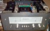
Here's a pic of the baby. The missing knob and button are just camera shy. They will return shortly. The second pic gives you a better idea of the nice contrast the meter backlights provide to the classic sliver look.

Will probably try to wrap this up over the weekend. The roommate is off in Chicago and I've got the place to myself until Sunday.
 

Attachments

  • 700m-10.jpg
    700m-10.jpg
    65.2 KB · Views: 177
  • 700m-11.jpg
    700m-11.jpg
    46 KB · Views: 170
Last edited:
That seriously KICKS ASS!

Way way cool!!!

Does my heart good to know that the old Sprague cap will have a home in a 700M.

:thmbsp: :thmbsp: :thmbsp: :banana: :banana: :beerchug: :drunk: :guitar: :guitar: :guitar:
 
Oh...the channel with 9mV offset might be tough to beat...that's a pretty damn decent reading. But, if you're like me, you want both channels the same. So...match carefully, and don't be suprised if the best you can get it with a homemade matched pair is 15mV or so.

Then again, if you look at the schematic, you can see that the tail current for the diff pair is a measily 0.5mA, so each diff pair transistor is flowing only 250µA(!!). This allows for very low base currents, which helps keep offset down, but it also means the diff pair has diddly-squat for drive capability...hence the next stage after the diff pair is an emitter-follower. ;)

Point being is that...with some really good high-gain transistors, base current will nearly become meaningless and offset has a good chance of staying lower than 10mV...which is about all you can possibly hope for with the design Kenwood gave you.
 
Keep posting Gonzo/EW, I'm following right along with you guys, inspiring me to rip my KA-9100 apart here soon and do some long overdue cap replacement on the PS supply board, EW already helped me with the driver boards, as always thanks Glenn. :)
 
ATM I'm sitting in front of the 700m with the left driver board (9mv offset) pulled and the faceplate flipped down (I *love* that feature!). I was going to pull the bias pot and diff pair but I think I'll just do the pot for now. Eventually I'll replace them but why screw with it. I don't like the odds EW just laid out so I think I'll just stay with 9mv. The right channel however, is going to get a new pair.

Found the source of the mystery hum. When you flip down the front panel, right in line with the two driver boards, there are three grounding wires screwed to the chassis (two on the left, one on the right). All three were mildly oxidized. A wave of the magic Dremel and a drop of ProGold put everything right. I thought I might have had another hum issue but it turned out to be a cheap RCA cable with a flaky shield.

So how does it sound so far? I don't want to fall victim to the "You hear what you want to hear" but she has performed admirably with the beater AR-4xs. Even heard a few new details on Cds I've owned for 20 years. When I get the offset and bias set, I'll hook them up to the "the good stuff" and let her rip.
 
Last edited:
Congratulations on bringing back a superb piece of gear!
I hope she will entertain you for a long time.
I haven't had the opportunity to hear that series of models, but have had a KR-9600 and the KA-9100 and still have (in system) a KT-7500.
How can I forget the Kenwood Basic C-2 in system now playing?
Kenwood made some GREAT sounding gear when they wanted to impress.
:thmbsp:
:banana:
 
Sorry if I'm annoying anybody with this thread. I'm posting multiple daily updates with every bit of progress just to try and inspire somebody else to rescue an abused amp, a wrecked receiver or trashed tapedeck. Mind you EW provided me with a lot of mods he performed on his but I don't think this would have been impossible for most AKers.

More importantly, I have an amp that's impressive in every sense of the word. It has a certain physical presence with the backlit blue-green VU meters. It just screams quality. Machined metal knobs and faceplate. The switches and pots click and turn with a very solid feel. I think I'm in love...

I replaced the factory bias pots and set the new ones to the same value. In both channels, the bias was at least 12mA low. :yikes:

My brother stopped by today and I tried to get him to put down his iPod and listen to something he doesn't have to stick in his ears. He barely turned the volume up above the normal TV volume. Oh well...

I just realized that this wasn't as expensive a task as it could have been. Others might have waited for a working one to show up but look at it this way. The caps almost certainly would have needed replacement, the OnSemi outputs are far more reliable and the input diffs would have drifted on any "working" unit from the average ebay seller. Besides, with all the mods EW suggested, she probably beats the original factory specs. Speaking of which, I need to print out something EW sent me. I'll have to do one last photo when everything is buttoned up.

One last question for EW. In one of your emails you suggested bypassing the filter caps on the high current supply with a Panasonic ECQ-E(B) metal polyester in about a 4.7µf 250V size, #P10987-ND. Exactly what is the benefit of this mod?
 
Last edited:
ESR (equivalent series resistance) is the impedence of the capacitor at a given frequency. Ideally, voltage sources should look like a dead short to AC signals (Thevenin's Theorem). Large electrolytics are essentially wound much like an inductor, and as ESR rises with rising frequency, the voltage source (the power supply caps) no longer 'look' like an ideal voltage source, and this can affect high frequency response and the ability to source current during brief transients. Adding a good quality film cap across the power supply capacitors ensures that the ESR remains low at all frequencies.

Sansui did this for years even on their mid-level stuff. Most other manufacturers didn't catch on till the mid 80's, by which time no one cared anymore. ;) But the high-end gear from manufacturers that most of us can't afford have also done it since Day 1.
 
The case of the rattling case... (film caps at 11)

Thanks for explaining the film bypass. I had seen the caps on Sansui gear and many posts suggesting them but nobody explained it in simple terms.

Before I had to take it off the bench and put it away for a few days (while I make space in either the bedroom or living room system), I cranked her up with the AR-4x speakers to a few CDs. Suddenly I was greeted with a raspy sound on low bass notes that sounded like nothing I'd ever heard before. I saw the 700m's meters jump and I almost freaked. After ruling out a few things like the woofer rattling and amp distortion, I figured out what it was.

As I mentioned earlier, this amp came from an abused home. Missing most case screws and the sheet metal cover was bent and dented. I did my best to straighten it out and found new screws. Turns out I didn't tighten it down enough. With an AR-4x less than a foot away, the little AR was exciting the cover into oscillation.

I'm not going to bother with replacing the shields on the left driver board and the relay board. Probably should redo the caps on the relay board as well (they look OK but they're no spring chickens). Once this kid gets settled into a system, its not going to move for a *long* time.
 
Last edited:
So, let me gets this correct, putting say a .01 uf 100v cap across the + and - terminals of the power supply caps will effectively keep ESR down to very low levels? I would imagine then using a good metallized polypropolene cap is the ideal choice in this situation? I think I would like to try this on a couple of my amps and see what the results are.
 
Keep posting...I'm getting the inspiration. :) I'm making a list of parts to recap my SX-828 and re-transistor the phono amp and preamp boards...there's a toasty tranny in the left channel on the preamp board. I need to get the #'s for them and see if there's a Zetex sub for them.

I like these threads, inspires me to head back downstairs and get some work done. :D Got my 838 to do too...offset goes all over the place and trips the protection. Phono stage has a bad transistor, too. She'll get all new 'lytics and small-signal trannies, too.

TP

PS - that blue backlighting on that amp is sweet!!! :banana:
 
Back
Top Bottom