• The move to the new server is done. There are some software and database maintenance updates in process. This has us passing the hat around to help out. We appreciate any donations. Seriously, even a dollar helps. The payment page may be found here - https://www.audiokarma.org/support.html

Kenwood Basic C1 Preamplifier Restoration/Upgrade

Phono Pre-Amp capacitance is 68pF.
Good info to have for proper manufacturers recommended MM cartridge loading.

ie: my tonearm wires plus headshell plus interconnect cables (mine are 4ft long) - total 100pF

Stanton 681se cartridge manufacturer loading specification is 275pF

Kenwood C1 phono preamp = 68pF
my Phono setup complete system capacitance equals exactly = 100pF
100pF + 68pF = 168pF

275pF - 168pF = 107pF

"For phono cartridge loading I would recommend either C0G types or polypropylene types."

with a Y splitter would add a COG type or polypropylene type of 100pF, as the dual female to one RCA splitter has a capacitance of around 7pF .

107pF - 7pF (RCA Splitter) - 100pF COG or polypropylene capacitor

(hits the nail on the head.)
 
Good Lawd I would not have a clue how to figure in all of that. I just slap on a cart and play with the switch to see what I think sounds best. I ain't no expert setting up turntables that is for sure!
 
Good Lawd I would not have a clue how to figure in all of that. I just slap on a cart and play with the switch to see what I think sounds best. I ain't no expert setting up turntables that is for sure!
It's more like therapy.
but without the BS.
 
Now that I can agree with. About to go in right now and fire up the CJ since I am breaking in a brand new set of KT88's. I feel like a lucky dude to have all this vintage Hi Fi. I got laying around here.
 
Flat Amp Stage
The stock flat amp stage op amp (IC1), a NJM2043, was replaced with a NJM2068DD op amp (a low-profile DIP socket was also installed). The stock capacitors in the input high-pass filter (C3, C4) were 1.0µF low leakage electrolytic capacitors and these were replaced with 1.0µF Panasonic stacked polyester film capacitors. The stock capacitors in the low-pass filter (C5, C6) were ordinary 10pF ceramic capacitors; the replacements were C0G capacitors of the same value. Similarly, the 68pF ceramic capacitors in the feedback loop (C11, C12) were replaced with C0G capacitors of the same value. The stock 220µF/6.3V polarized electrolytic capacitors in the feedback loop (C7, C8) were replaced with Nichicon Muse ES bi-polar electrolytic capacitors of the same capacity but higher voltage (16V) rating. The output capacitors (C13, C14) were 22µF bi-polar electrolytic types and these were replaced with Nichicon Muse ES bi-polar electrolytic capacitors of the same capacity.

Tone Amp Stage
The stock tone amp op amp (IC2), a NJM4560, was replaced with a NJM2068DD op amp (a low-profile DIP socket was also installed). The stock capacitors in the input high-pass filter (C19, C20) for IC2 were 1.0µF low leakage electrolytic capacitors and these were replaced with 1.0µF Panasonic stacked polyester film capacitors. Similarly, the stock capacitors in the tone control inputs (C21, C22), which were 1.0µF low leakage electrolytic capacitors, were replaced with 1.0µF Panasonic stacked polyester film capacitors. The 10pF ceramic capacitors in the feedback loop (C27, C28) were replaced with C0G capacitors of the same value. The ordinary ceramics at the output of the tone amp stage (C29, C30) were replaced with C0G capacitors of the same value. The final output high pass filter capacitors (C25, C26) were 47µF bi-polar electrolytic types and these were replaced with Nichicon Muse ES bi-polar electrolytic capacitors of the same capacity. Also, the stock 1.2kohm load resistors (R41 and R42) were replaced with 56.2kohm metal film resistors.

 
This Kenwood Basic C1 is the matching preamplifier to AK member Unican Eric's Kenwood M1. The M1 received a complete restoration and upgrade (http://www.audiokarma.org/forums/showthread.php?t=608332) and the same was planned for the C1.

The restoration/upgrade included the following:
1. Replacement all of the power supply electrolytic capacitors with higher spec. 105°C, low ESR types (increasing capacity where appropriate and possible).
2. Adjustment of the power supply rail voltages to ~16V for the line stage and ~18V for the phono stage (the original rail voltages exceed the maximum specified for the op amps).
3. Upgrading the op amps to NJM2068DD (line stage) and NJM4580DD (phono stage).
4. Replacement of the signal path capacitors, with either "audio grade" bipolar electrolytic capacitors, film types or C0G types, as appropriate.

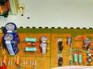
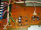
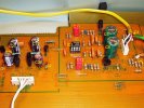
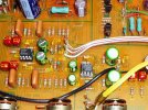
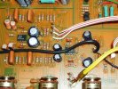
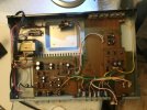
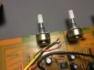
Here are some pictures of the Kenwood Basic C1 preamplifier as first received:


Why new IC sockets? Do the upgraded ones not fit the originals?
They fit fine. I am sure some weld them right on in. They are used in case one wants to roll op amps. Try different ones to see what you like best in that position. Kinda like rolling tubes.
 
Finished my Kenwood C1 pre-amp upgrade as per LeeStereo's excellent post.
thank you

Would also like to thank Antiskate for his POM submission.

Mouser # Mfr. # Desc. Order Qty. Customer Part #
647-UES1E470MPM UES1E470MPM Aluminum Electrolytic Capacitors - Leaded 25volts 47uF 85c 10x12.5 5LS 2 TA C25, C26
575-113308 110-13-308-41-001000 IC & Component Sockets 8P GLD PIN GLD CONT 4 8 pin IC Sockets
647-UPW1H010MDD UPW1H010MDD Aluminum Electrolytic Capacitors - Leaded 50volts 1uF 5x11 20% 2LS 2 PRE C45
647-UFG1C221MPM1TD UFG1C221MPM1TD Aluminum Electrolytic Capacitors - Leaded 220uF 16 Volts 20% 2 TA C7, C8
667-ECQ-V1H334JL ECQ-V1H334JL Film Capacitors .33uF 50V 5% 2 PRE C17, C18
505-MKS2B043301HJSSD MKS2B043301H00JSSD Film Capacitors 3.3uF 50 Volts 5% 2 PRE C11, C12
647-UPW1C222MHD UPW1C222MHD Aluminum Electrolytic Capacitors - Leaded 16volts 2200uF 12.5x25 20% 5LS 2 PRE C5, C6
581-SR151A101JAR SR151A101JAR Multilayer Ceramic Capacitors MLCC - Leaded 100volts 100pF 5% C0G 2 PRE C1, C2
513-NJM4580DD NJM4580DD Audio Amplifiers Dual 1 PRE IC1
647-UPW1V221MPD UPW1V221MPD Aluminum Electrolytic Capacitors - Leaded 35volts 220uF 10x12.5 '20% 5LS 2 PRE C27, C28
647-UPW1V101MPD1TD UPW1V101MPD1TD Aluminum Electrolytic Capacitors - Leaded 100uF 105c 20% 35V 2 PRE C25, C26
78-BZX85B18 BZX85B18-TR Zener Diodes 18 Volt 1.3 Watt 2% 2 PRE D1, D2
603-MFR-25FBF52-56K2 MFR-25FBF52-56K2 Metal Film Resistors - Through Hole 56.2K OHM 1/4W 1% 4 TA R41, R42
581-SR151A470JAR SR151A470JAR Multilayer Ceramic Capacitors MLCC - Leaded 100volts 47pF 5% C0G 2 TA C29, C30
647-UES1H220MPM UES1H220MPM Aluminum Electrolytic Capacitors - Leaded 50volts 22uF 85c 10x12.5 5LS 2 TA C13, C14
581-SR151A100JAATR1 SR151A100JAATR1 Multilayer Ceramic Capacitors MLCC - Leaded 100V 10pF 5% Radial 4 TA C5, C6, C27, C28
581-SR151A680JAATR1 SR151A680JAATR1 Multilayer Ceramic Capacitors MLCC - Leaded 100volts 68pF 5% 2 TA C11, C12
505-MKS2C041001FJC00 MKS2C041001F00JC00 Film Capacitors 1uF 63 Volts 5% 10 TA C3,4,19,20,21,22
513-NJM2068DD NJM2068DD Operational Amplifiers - Op Amps Dual Low Noise 2 TA IC1, IC2
512-UF4005 UF4005 Rectifiers 600V 1a Rectifier Glass Passivated 2 TA D1, D2
78-BZX85B16-TAP BZX85B16-TAP Zener Diodes 16 Volt 1.3 Watt 2% 2 TA D6, D7
647-UPW1C101MED UPW1C101MED Aluminum Electrolytic Capacitors - Leaded 16volts 100uF 105c 1 TA C51
647-UPW1C330MDD UPW1C330MDD Aluminum Electrolytic Capacitors - Leaded 16volts 33uF 5x11 20% 2LS 1 TA C50
647-UPW1C470MDD1TD UPW1C470MDD1TD Aluminum Electrolytic Capacitors - Leaded 47uF 16 Volts 20% 2 TA C48, C49
647-UPW1E471MPD UPW1E471MPD Aluminum Electrolytic Capacitors - Leaded 25volts 470uF 10x16 20% 5LS 3 TA C45, C46, C47
647-UPW1V222MHD UPW1V222MHD Aluminum Electrolytic Capacitors - Leaded 35volts 2200uF 16x31.5 20% 7.5 2 TA C43,C44
653-G5V-2-H1-DC9 G5V-2-H1-DC9 Low Signal Relays - PCB ThruHole Hi-Sens DPDT 9VDC 150mW Seal 1 Relay


Just copied and pasted on Mousers website and everything was filled out.
total with shipping $90.
Only one back order item, which I purchased from DigiKey.

How to solder.

The best video instructions I've found.
Excellent like to thank these guys too.


Never soldered on circuit boards before.
Wanted it to be less of a hassle so bought myself a Soldering station on Amazon - $76

TOAUTO DS90 Soldering Station.​

This kit comes with a solder sucker, they really work well and along with tge solder wick are invaluable.
Get yourself a pair of Flush Cutters Side Cutters to cut the extra leads after they have been soldered to the circuit board.
Have solder Wick to suck up old solder, use flux paste on Wick.
Also bought a silicone soldering mat. $30

60cm x 35cm Silicone Soldering Mat (23.6 x 13.8 inch) Large Silicone Repair Mat Heat Resistant 500°C Fireproof Work Mat​

I have a microscope for turntable cartridges, came in very handy as this is pretty detailed work. $28

Digital Microscope, AOPICK Pocket Microscope Portable Handheld Microscopes with Adjustable Stand 50X-1600X Magnification, USB​

Had a incandescent counter clamping work light, was able to direct it exactly where it needed to be.

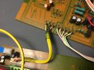
Disconnected all the wire leads on the wire wrap posts.
this is a must as your going to have to flip the circuit boards over.
Take lots of pictures and ID with felt pen just felt marks on wire and numbers on circuit board works.
Cleaning off solder flux paste, it's corrosive so must be cleaned off circuit board.
Have a toothbrush and isopropyl alcohol and a clean lint free cloth for placing over where you applied isopropy alcohol to clean and dry board, after you apply the isopropyl acohol with the toothbrush place the cloth on wet area and use toothbrush on cloth to dry area.

Thankful for the IC standoff saved on concern over over heating the heat sensitive IC's.
Amateur soldering so trying to keep the time to apply heat to as little as possible.

As I was going just used AntiSkates printed list that shows the circuit board location and component number.
Flat Amp, Phono board, Power supply board and so on.
used those Component ID number against Mousers list provided by Mouser with your order.
Each component was bagged independently as per type with multiples in same plastic bag.
Marked up each bag with its corresponding circuit board number, and placed old components in same bag.
Don't get confused over which component goes on a particular portion of the circuit board.
AntiSkate has each as above identified.

it gets easier as you go, less bags of components to deal with.


Thank You
Ben

 
Last edited:
Pics
 

Attachments

  • IMG_1778.jpeg
    IMG_1778.jpeg
    121.5 KB · Views: 39
  • C1 Power Supply Upgrade AK label.jpeg
    C1 Power Supply Upgrade AK label.jpeg
    186 KB · Views: 34
  • C1 Power Supply Original.jpeg
    C1 Power Supply Original.jpeg
    198.6 KB · Views: 32
  • C1 Phono Stage Original.jpeg
    C1 Phono Stage Original.jpeg
    217.9 KB · Views: 35
  • C1 Phono Stage Upgrade AK label.jpeg
    C1 Phono Stage Upgrade AK label.jpeg
    211.4 KB · Views: 38
  • C1 Line Stage Upgrade AK label.jpeg
    C1 Line Stage Upgrade AK label.jpeg
    227 KB · Views: 37
  • C1 Line Stage Original.jpeg
    C1 Line Stage Original.jpeg
    234.7 KB · Views: 36
More the wire posts are simply tinned wire wrapped around the posts.
They Will unwrap.
The ground wire that has a plastic cover over the bare conductor is brittle, be cautious with those they will break but that's handy, you have a soldering gun.
 

Attachments

  • IMG_1770.jpeg
    IMG_1770.jpeg
    103.8 KB · Views: 40
  • IMG_1773.jpeg
    IMG_1773.jpeg
    121.7 KB · Views: 37
  • IMG_1778.jpeg
    IMG_1778.jpeg
    121.5 KB · Views: 35
  • IMG_1774.jpeg
    IMG_1774.jpeg
    113.5 KB · Views: 40
The restoration/upgrade included the following:
1. Replacement all of the power supply electrolytic capacitors with higher spec. 105°C, low ESR types (increasing capacity where appropriate and possible).
2. Adjustment of the power supply rail voltages to ~16V for the line stage and ~18V for the phono stage (the original rail voltages exceed the maximum specified for the op amps).
3. Upgrading the op amps to NJM2068DD (line stage) and NJM4580DD (phono stage).
4. Replacement of the signal path capacitors, with either "audio grade" bipolar electrolytic capacitors, film types or C0G types, as appropriate.
How is step #2 done? Is it described anywhere? Did this upgrade earlier but did not recall doing step#2 so I am missing the big part of it?
 
How is step #2 done? Is it described anywhere? Did this upgrade earlier but did not recall doing step#2 so I am missing the big part of it?
You replace the zener diodes to get the voltage aligned with the opamps. if you plan to use the existing opamps, you can leave this alone.

i used 2068DD opamps in my C2 and had to lower the power supply voltage.
 
@EC1 I have done up quite a few C1's and 2's. I do not worry with changing the diodes out unless as @rickl said I upgrade to the newer op amps. If I do not use newer op amps I usually just leave them alone. For just a electrolytic upgrade let's say.
 
So there is no physical turning or adjusting of somethings, just to change out the diodes? Thx for the clarification.
 
Back
Top Bottom