

You are using an out of date browser. It may not display this or other websites correctly.
You should upgrade or use an alternative browser.
You should upgrade or use an alternative browser.
Kenwood Basic C1 Preamplifier Restoration/Upgrade
- Thread starter Leestereo
- Start date

Hi
Hopefully someone still monitors this thread
I have a couple questions about upgrading the C1. I'm a bit of an amateur but enjoy having a tinker.
I picked up a C1 that has had the power side of the amp rebuilt with a toroidal transformer, new fuse and new RCA outputs. I don't think anything on the board has been touched, or it at least doesn't appear to be. As it is I think it's a great sounding unit pair with a Sony TA-N55ES
I'm curious about the following:
Thanks in advance!
Hopefully someone still monitors this thread
I have a couple questions about upgrading the C1. I'm a bit of an amateur but enjoy having a tinker.
I picked up a C1 that has had the power side of the amp rebuilt with a toroidal transformer, new fuse and new RCA outputs. I don't think anything on the board has been touched, or it at least doesn't appear to be. As it is I think it's a great sounding unit pair with a Sony TA-N55ES
I'm curious about the following:
- Is it worth just upgrading the opamps?
- Does the power section make a difference to the upgrades discussed here?
- My opamp model numbers don't appear to match what the OP has listed. 2043DD JRC 4018 on both Tone amp and flat amp stage. 4560DN JRC 4311 on the phono stage. I'm now not sure if these are stock or maybe have been replaced?
Thanks in advance!
I just did mine except the phono section last week. And this is my IC1 and IC2 as you can see in the photos below. Mine appears to be all original untouched until now. So there might just be different production things. Not sure.
I don’t have TT so I think might not be necessary to do the phono section? I am doing 3 preamps at about same time, Proton 1100, ADCOM GFP 565 and C1. Very curious to see the result myself. But I don’t have experienced ears, all sounds wonderful to me.
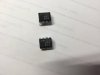
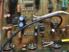
I don’t have TT so I think might not be necessary to do the phono section? I am doing 3 preamps at about same time, Proton 1100, ADCOM GFP 565 and C1. Very curious to see the result myself. But I don’t have experienced ears, all sounds wonderful to me.
That's so strange. Obviously there are some manufacturing differences. I have the same opamps on both IC1 and IC2 and the different one was on the phono stage. I thought this may be a gain thing to keep gain similar to RCA inputs. That doesn't seem to be the case!
I'll just install some sockets and have a play with opamps I think
I'll just install some sockets and have a play with opamps I think


Phaceless56
Active Member
almost done with my C1 restore can someone tell me where this cap goes
Extra Under board 100uf 25V 100uf/25v 647-UPW1E101MED
Thank you
Extra Under board 100uf 25V 100uf/25v 647-UPW1E101MED
Thank you

i bought a c1 awhile back just so i could try this upgrade. the c1 was boring before the upgrade and it's still boring after. i even had the parts in stock and consider it a waste of time and money.
if i were to name one thing that stood out about the c1, it is the lackluster variable loudness control, i like a fat beefy bottom end and this just does not do it for me no matter which amp i've paired it with. (ev7200,adcom gfa 5300,nad 2140 and b&k vmr654)
sources were cd thru a cal sigma 2 and vinyl.
just my opinion.
if i were to name one thing that stood out about the c1, it is the lackluster variable loudness control, i like a fat beefy bottom end and this just does not do it for me no matter which amp i've paired it with. (ev7200,adcom gfa 5300,nad 2140 and b&k vmr654)
sources were cd thru a cal sigma 2 and vinyl.
just my opinion.
After completing a relatively successful Leestereo upgrade (thank you, great info) to my C1 I am not getting any sound from the Phono Stage. Aux no problem.
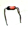
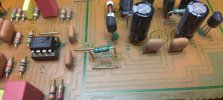
I have found a scorched resistor on the regulated supply to the phono on J20 which is a jumper on other units. Anyone know why some have it as a jumper and others, including mine, have it as a resistor. Also I have no idea what resistance the resistor should be. It's not on my schematic. Any help would be appreciated.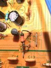
I have found a scorched resistor on the regulated supply to the phono on J20 which is a jumper on other units. Anyone know why some have it as a jumper and others, including mine, have it as a resistor. Also I have no idea what resistance the resistor should be. It's not on my schematic. Any help would be appreciated.
Attachments

Phaceless56
Active Member
I'm looking at the service manual that is a jumper not sure why someone would put a resister there maybe someone else can chime in. One other thing check the transistor next to that resistor I believe that Q8 in the photo it looks like it is coming apart.
Got a feeling that I put the Electrolytic under the PCB with the wrong polarity, hence the burned out resistor. I'll check the transistor as well.I'm looking at the service manual that is a jumper not sure why someone would put a resister there maybe someone else can chime in. One other thing check the transistor next to that resistor I believe that Q8 in the photo it looks like it is coming apart.
Attachments
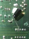
design change mid production run. it's factoryI'm looking at the service manual that is a jumper not sure why someone would put a resister there maybe someone else can chime in. One other thing check the transistor next to that resistor I believe that Q8 in the photo it looks like it is coming apart.

crispycircuit
Super Member
Does anyone have a schematic for the C1?
Xenon-Codex
Active Member
Hifiengine has: https://www.hifiengine.com/manual_library/kenwood/basic-c1.shtml
I know this is cheesy but I have a chance to get a really nice sounding and new looking C2. It does have some drop outs in the balance control.
I would like to do this rebuild but following the links to various components listed throughout this thread are not available or only available in quantity quotes.
Is there a place or has anyone consolidated all of these mods into one thread that would make it easier to follow. The PS section is really hard to follow. I can read, desolder, resolder and the like but no genius at electronics. Aware of the basics but I have no my limitations.
If there was a manual available along with a list of what components were being replaced with what new components, it would sure help out those like me who would like to join the party rather than just look in at the window.
Sure would like to get a schematic and/or service manual.
Suggestions??? Help???
Thanks in advance.
I would like to do this rebuild but following the links to various components listed throughout this thread are not available or only available in quantity quotes.
Is there a place or has anyone consolidated all of these mods into one thread that would make it easier to follow. The PS section is really hard to follow. I can read, desolder, resolder and the like but no genius at electronics. Aware of the basics but I have no my limitations.
If there was a manual available along with a list of what components were being replaced with what new components, it would sure help out those like me who would like to join the party rather than just look in at the window.
Sure would like to get a schematic and/or service manual.
Suggestions??? Help???
Thanks in advance.
Check out DRM Audio. He has everything you might need to completely restore the Kenwood Basic line, including the C2. Super high quality designs. He even has the loudness/balance board that would address the item you mentioned. I have 3 C2’s and have installed his parts I needed in each one.