• The move to the new server is done. There are some software and database maintenance updates in process. This has us passing the hat around to help out. We appreciate any donations. Seriously, even a dollar helps. The payment page may be found here - https://www.audiokarma.org/support.html

Kenwood Basic C1 Preamplifier Restoration/Upgrade

The PS section is really hard to follow.
If there was a manual available along with a list of what components were being replaced with what new components, it would sure help out those like me who would like to join the party rather than just look in at the window.

Suggestions??? Help???
this is for the C2 per Thx1326. I can delete if it is confusing.

Here is the PS section for the line level
1705631754191.png

if you want to use an OPAMP that needs a lower supply voltage, update D13/D14. I think I used 15v or 16v zeners.

Also you can see c77/c78. these are the main supply caps. I'd probably use 2200/50v.

here is the phono PS:
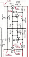
1705632412449.png


if you want to update the phono section opamp, D11/12 may need to change and c63-c68 for the phono PS. I don't recall what others used but I'd probably use the same values.

UPW series should work. check digikey or mouser.

BTW, I think my C2 thread has this (I didn't read it) and links to replacing the balance pot with resistors. Or DRM audio for a new balance pot per dave's post.
 
Last edited:
Is AC-DC rectification in the C2 done with single diodes? If so, can someone identify them? Also has anyone thought of replacing the single diodes with a full bridge rectifier? If so, where did you make the connections?

Thanks.
 
Is AC-DC rectification in the C2 done with single diodes? If so, can someone identify them?
Looks like D19 and D20. Going to a fullwave bridge will increase the incoming "DC". What effect will this have of the rest of the regulated psu??? eg, downstream D21??? Do you have any audible hum (50/60Hz) that a fullwave might reduce?
 
Since I am doing a recap and have the unit open, I figured any noise reduction would be good. Would replacing the two standard diodes with Ultra-Fast Stealth Schottke diodes be of benefit here? At worst, it couldn't hurt?? Would it be feasible to do the same for all: D 15, 18, 19, 20, 21, 22?
 
Going to a fullwave bridge will increase the incoming "DC"
Thinking about this some more, above is probably pure bs, ie, if caps were ideal, no loss/leakage and no load then the voltages would be the same.

Would replacing the two standard diodes with Ultra-Fast Stealth Schottke
Yeah, I went through the ultra fast diodes, mostly intended for SMPs, didn't pickup any significant improvement.
There is a school of thought that "Soft Recovery diodes" has benifits in audio, I've yet to try.

Certainly implement suggestions in this thread, ie, opamp/socket, modification to power supply/zeners
 
Hi there,

I have a Basic C1 incoming that I like to recap, following the excellent advice in this thread. I have a copy of the C1 service manual, and notice VR1, VR2 and VR3, but no procedure for adjustments. Can anyone advice on how to finalize preamp adjustments (if any) following recap?

Thanks!
 
VR1,2,3 are pots for the controls on the front of the unit. No adjustment until you re cap and start playing it. Then for treble, bass, etc.
 
I have a C1 on the way that i bought and will be here in a few days. Has been modified but not sure of how much. But states it has
opamps installed are JRC NJM4580DD in the phono amp ,, and NJM2068DD in the flat amp, tone amp, and filter amp. And new caps. Here is a pic, but will know more when it gets here on what was done.
 

Attachments

  • nvvkobiey6i1dnev0mux.jpg
    nvvkobiey6i1dnev0mux.jpg
    142.3 KB · Views: 22
It's a great preamp. When refurbished and like new, they sound great.

It won't make bad speakers sound good, but it will make good speakers sound great.
 
Seller sent this in message to me of what other parts he changed and the best he could remember.

Replaced all the Zener diodes, changed out all the lesser ceramic capacitors for c0g, replaced electrolytic caps with fresh nichicon and Panasonics, bipolar in signal path. Replaced small film caps, I think they are Kemet polypropylene now. Replaced the output relay as well as I recall. I played around with some different opamps at the time but decided the JRC sounded “right” to my ear.
 
In the C1 preamplifier, it is the output load resistors (R41/R42) for the final op amp that are changed to 56.2kohm resistors. This will not affect the gain of the circuit. In the C2, the corresponding resistors are R55/R56 and they are already specified as 56kohm.
These resistors R41 and R42 are located in the power supply for the EQ Amp?
 
Back
Top Bottom