guy232
Member
Note: Initial post is kinda long, it documents what I have done so far. Any advice on how to better do anything detailed thus far is very welcome. Future update posts will be shorter, dealing with 1-2 tasks presently at hand & likely including questions etc.
Foreword (Main post starts at the photo below)
Hello all, was unexpectedly given the ~47lb KR-9940 a week ago. Despite being the top of the model line, there isn't too much repair talk out there for this. My first non-stk module unit. I'm pretty new to this so i'll probably be encountering some problems that may be trivial to most but new to me, i'll be using this thread for the following:
LINK TO SERVICE MANUAL PDF: https://www.hifiengine.com/manual_library/kenwood/kr-9940.shtml
Project start, looking inside, first inspection/probing

The unit arrived in good shape. Supposedly worked fine in the past but was packed up & put away in a dry closet for many years until now.
Opening up (including face plate):
Removed 2x side wood, top cover, bottom cover, knobs.
Face plate:
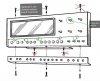
The upper lamp pc board is screwed to the face with 2 screws OR you can disconnect the lamp board via the connector. CAUTION: If this is the first time, the connector pins are very weak in this area and the connector is likely siezed, risking ripping out the pins. I opted to remove the lamp board via the 2 screws on the face plate and sit them aside, we go back to them after we get the face off.
The manual is wrong and doesn't show the right things for removing face for me, some screws (including their mounting spots) didn't even exist such as the 2 on the underside middle of the main bezel. 12mm hex w/ washer on selector knob.
Dealing w/ lamp board connectors:
I laid down some rags and propped up the board so I could soak the pins. I sprayed deoxit into syringe, dripped into each hole of connector and let it soak for a few hours, maybe it doesn't need that much time. A warm-hot air may help if you're in a cold climate. Next pinched each ends of the connectors and rocked horizontally just enough to feel some give. Then pulled straight off. No visible flexing or movement of pins were noticed.
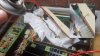
NOTE: Pic below is just for example, the connectors aren't fully seated here
Initial inspection (brief power up via DBT, bias check)
No visibly damaged components or heat stress spotted anywhere. Very minimal amount of dust. Largest piece of foreign debris was a hair. I did see a couple broken white plastic bead style cable ties but they were in the right positions, maybe broke by themselves. A bendable metal black cable holder was unbent, so probably someone has been in this unit before.
Plugged into DBT, powered on fine, let it idle for 5min, noticed a little heat on part of the heatsink, nothing major. Maybe I made the wrong choice but since the heatsink was unevenly heating I thought it may be best to check and adjust bias.
Bias: With unit directly connected to mains, powered on & all controls set to unloaded idle state, measure across the 4 emitter resistors of Q2, Q4, Q6, Q8. Had some trouble with this because the resistors were initially tucked about half way inside the heatsink very cramped & covered by wires.
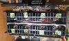
@rickl helped out by showing me a pic of what he did and I simply had to apply a little force to bend the resistors into position to easily attach my leads to. I used some long grabber hooks, I think croc clips would be risky if one pops off. You don't have to directly clip onto the resistors, a 3 pronged terminal strip is screwed into each transistor, I clipped onto this prong. My other clip was onto the 2nd lead of the resistor itself (this lead connects to the emitter of the transistor)
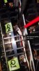
With device unpowered, I turned on meter to make sure the resistance seemed right so I knew I was connected across the resistor. I then powered up on DBT to ensure I was clipped safely. I then removed DBT, powered up and adjusted each of the four VR1-4 to 25mV and let idle a bit til stabilized. The heatsink now idles at an even and low temperature.
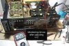
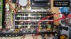
Up next:
Now that the unit is idling at an even/low temperature I think the next step is probably going to be inspecting voltages on some of the power supply boards. Will update on that in next post.
List of links to sites/forums that talk about repairing the 9940: Optional content for fellow owners. Despite digging deep over the span of a couple days I didn't find very much info online so I figured i'd share the list I made for myself. Searched archived pages, even used some non-english search engines in hopes of finding translateable stuff. If you know of any links please mention or PM and i'll add it here.
(will be filling this out soon)
Foreword (Main post starts at the photo below)
Hello all, was unexpectedly given the ~47lb KR-9940 a week ago. Despite being the top of the model line, there isn't too much repair talk out there for this. My first non-stk module unit. I'm pretty new to this so i'll probably be encountering some problems that may be trivial to most but new to me, i'll be using this thread for the following:
- Notes
- Discussing future plans of action
- Any cool details, service bulletins or potentially useful facts about the KR-9940 are extremely welcomed
- Compiling list of different links to (some are ancient/archived) posts/websites discussing potentially useful KR-9940 repair info at the bottom of this first post
- Any critiques or advice welcome, i'm open minded and always up for learning how to do something better
LINK TO SERVICE MANUAL PDF: https://www.hifiengine.com/manual_library/kenwood/kr-9940.shtml
Project start, looking inside, first inspection/probing
The unit arrived in good shape. Supposedly worked fine in the past but was packed up & put away in a dry closet for many years until now.
Opening up (including face plate):
Removed 2x side wood, top cover, bottom cover, knobs.
Face plate:
The upper lamp pc board is screwed to the face with 2 screws OR you can disconnect the lamp board via the connector. CAUTION: If this is the first time, the connector pins are very weak in this area and the connector is likely siezed, risking ripping out the pins. I opted to remove the lamp board via the 2 screws on the face plate and sit them aside, we go back to them after we get the face off.
The manual is wrong and doesn't show the right things for removing face for me, some screws (including their mounting spots) didn't even exist such as the 2 on the underside middle of the main bezel. 12mm hex w/ washer on selector knob.
Dealing w/ lamp board connectors:
I laid down some rags and propped up the board so I could soak the pins. I sprayed deoxit into syringe, dripped into each hole of connector and let it soak for a few hours, maybe it doesn't need that much time. A warm-hot air may help if you're in a cold climate. Next pinched each ends of the connectors and rocked horizontally just enough to feel some give. Then pulled straight off. No visible flexing or movement of pins were noticed.
NOTE: Pic below is just for example, the connectors aren't fully seated here
Initial inspection (brief power up via DBT, bias check)
No visibly damaged components or heat stress spotted anywhere. Very minimal amount of dust. Largest piece of foreign debris was a hair. I did see a couple broken white plastic bead style cable ties but they were in the right positions, maybe broke by themselves. A bendable metal black cable holder was unbent, so probably someone has been in this unit before.
Plugged into DBT, powered on fine, let it idle for 5min, noticed a little heat on part of the heatsink, nothing major. Maybe I made the wrong choice but since the heatsink was unevenly heating I thought it may be best to check and adjust bias.
Bias: With unit directly connected to mains, powered on & all controls set to unloaded idle state, measure across the 4 emitter resistors of Q2, Q4, Q6, Q8. Had some trouble with this because the resistors were initially tucked about half way inside the heatsink very cramped & covered by wires.
@rickl helped out by showing me a pic of what he did and I simply had to apply a little force to bend the resistors into position to easily attach my leads to. I used some long grabber hooks, I think croc clips would be risky if one pops off. You don't have to directly clip onto the resistors, a 3 pronged terminal strip is screwed into each transistor, I clipped onto this prong. My other clip was onto the 2nd lead of the resistor itself (this lead connects to the emitter of the transistor)
With device unpowered, I turned on meter to make sure the resistance seemed right so I knew I was connected across the resistor. I then powered up on DBT to ensure I was clipped safely. I then removed DBT, powered up and adjusted each of the four VR1-4 to 25mV and let idle a bit til stabilized. The heatsink now idles at an even and low temperature.
Up next:
Now that the unit is idling at an even/low temperature I think the next step is probably going to be inspecting voltages on some of the power supply boards. Will update on that in next post.
List of links to sites/forums that talk about repairing the 9940: Optional content for fellow owners. Despite digging deep over the span of a couple days I didn't find very much info online so I figured i'd share the list I made for myself. Searched archived pages, even used some non-english search engines in hopes of finding translateable stuff. If you know of any links please mention or PM and i'll add it here.
(will be filling this out soon)
Last edited:

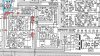
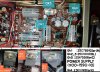

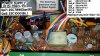
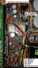


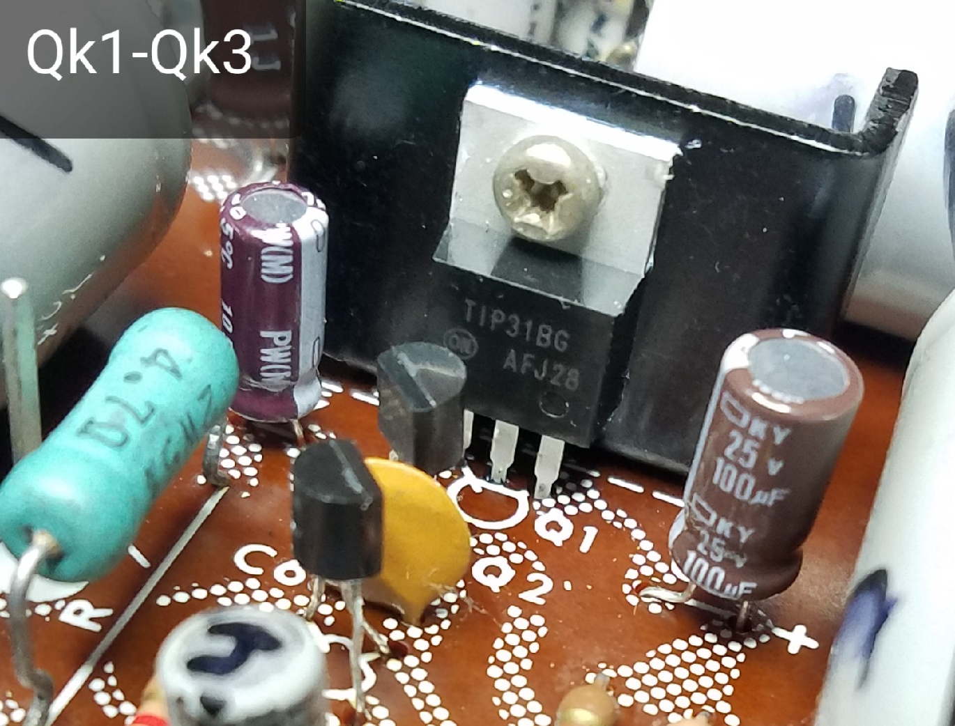


 I then cleaned and lubed all the pots and got it working - sounded really nice but I noticed the right rear channel was not as robust as the other 3 channels and the VU meter showed that as well - but I used anyway until yesterday when I turned it on and it took longer than norm to hear the relays come in and when they did I noticed a HUM in all channels in all modes w/ nothing but power and speakers connected - still plays music when turned up above the HUM but the right rear channel is still lower. I read many that feel it is the filter caps but there is no sign of leakage or bulging so I am slow to want to order them - I am hoping to get a scope and working a deal out for Speakers and a Turntable, if that fails I am going to do a wholesale swap of all the caps on the power supply bds saving the two 15000uf 50V caps for last - again thanks for the postings, it was very informative.