Note: Initial post is kinda long, it documents what I have done so far. Any advice on how to better do anything detailed thus far is very welcome. Future update posts will be shorter, dealing with 1-2 tasks presently at hand & likely including questions etc.
Foreword (Main post starts at the photo below)
Hello all, was unexpectedly given the ~47lb KR-9940 a week ago. Despite being the top of the model line, there isn't too much repair talk out there for this. My first non-stk module unit. I'm pretty new to this so i'll probably be encountering some problems that may be trivial to most but new to me, i'll be using this thread for the following:
Much thanks to @rickl for helping out with some initial questions and pics. I'll be includig any key details from that here.
- Notes
- Discussing future plans of action
- Any cool details, service bulletins or potentially useful facts about the KR-9940 are extremely welcomed
- Compiling list of different links to (some are ancient/archived) posts/websites discussing potentially useful KR-9940 repair info at the bottom of this first post
- Any critiques or advice welcome, i'm open minded and always up for learning how to do something better
LINK TO SERVICE MANUAL PDF: https://www.hifiengine.com/manual_library/kenwood/kr-9940.shtml
Project start, looking inside, first inspection/probing
View attachment 1634071
The unit arrived in good shape. Supposedly worked fine in the past but was packed up & put away in a dry closet for many years until now.
Opening up (including face plate):
Removed 2x side wood, top cover, bottom cover, knobs.
Face plate:
The upper lamp pc board is screwed to the face with 2 screws OR you can disconnect the lamp board via the connector. CAUTION: If this is the first time, the connector pins are very weak in this area and the connector is likely siezed, risking ripping out the pins. I opted to remove the lamp board via the 2 screws on the face plate and sit them aside, we go back to them after we get the face off.
The manual is wrong and doesn't show the right things for removing face for me, some screws (including their mounting spots) didn't even exist such as the 2 on the underside middle of the main bezel. 12mm hex w/ washer on selector knob.
View attachment 1634113
Dealing w/ lamp board connectors:
I laid down some rags and propped up the board so I could soak the pins. I sprayed deoxit into syringe, dripped into each hole of connector and let it soak for a few hours, maybe it doesn't need that much time. A warm-hot air may help if you're in a cold climate. Next pinched each ends of the connectors and rocked horizontally just enough to feel some give. Then pulled straight off. No visible flexing or movement of pins were noticed.
NOTE: Pic below is just for example, the connectors aren't fully seated here
View attachment 1634121
Initial inspection (brief power up via DBT, bias check)
No visibly damaged components or heat stress spotted anywhere. Very minimal amount of dust. Largest piece of foreign debris was a hair. I did see a couple broken white plastic bead style cable ties but they were in the right positions, maybe broke by themselves. A bendable metal black cable holder was unbent, so probably someone has been in this unit before.
Plugged into DBT, powered on fine, let it idle for 5min, noticed a little heat on part of the heatsink, nothing major. Maybe I made the wrong choice but since the heatsink was unevenly heating I thought it may be best to check and adjust bias.
Bias: With unit directly connected to mains, powered on & all controls set to unloaded idle state, measure across the 4 emitter resistors of Q2, Q4, Q6, Q8. Had some trouble with this because the resistors were initially tucked about half way inside the heatsink very cramped & covered by wires.
View attachment 1634387
@rickl helped out by showing me a pic of what he did and I simply had to apply a little force to bend the resistors into position to easily attach my leads to. I used some long grabber hooks, I think croc clips would be risky if one pops off. You don't have to directly clip onto the resistors, a 3 pronged terminal strip is screwed into each transistor, I clipped onto this prong. My other clip was onto the 2nd lead of the resistor itself (this lead connects to the emitter of the transistor)
View attachment 1634388
With device unpowered, I turned on meter to make sure the resistance seemed right so I knew I was connected across the resistor. I then powered up on DBT to ensure I was clipped safely. I then removed DBT, powered up and adjusted each of the four VR1-4 to 25mV and let idle a bit til stabilized. The heatsink now idles at an even and low temperature.
View attachment 1634389
View attachment 1634390
Up next:
Now that the unit is idling at an even/low temperature I think the next step is probably going to be inspecting voltages on some of the power supply boards. Will update on that in next post.
List of links to sites/forums that talk about repairing the 9940: Optional content for fellow owners. Despite digging deep over the span of a couple days I didn't find very much info online so I figured i'd share the list I made for myself. Searched archived pages, even used some non-english search engines in hopes of finding translateable stuff. If you know of any links please mention or PM and i'll add it here.
(will be filling this out soon)


You are using an out of date browser. It may not display this or other websites correctly.
You should upgrade or use an alternative browser.
You should upgrade or use an alternative browser.
Kenwood KR-9940 Quad Amp Project - Notes/Questions
i am also going to be doing some repairs/upgrades to my kenwood kr-8840 and seeking any information also. looks like some very good info here.Evidently no service manual for 8840 other then the 9940..so i,m limping along..Inoticed the other gentleman listed his equip. As far as quad the 8840 , JVC VL-5 Lay
fayette SQ-W 4 kenwood D series speakers 2 777 and 2 888 So yes I will be using my quad setup. As far as stereo Equip. I just finished the Lee Stereo upgrade on my Sansui AU-717 and I have the matching tuner.. sony cd player..anyway I seem to have lost the R/R chanel I can see the meter is moving and hear a slight bit of sound but thats about it. So I thought I would check the main first..then attempt to set the bias and see what happens
fayette SQ-W 4 kenwood D series speakers 2 777 and 2 888 So yes I will be using my quad setup. As far as stereo Equip. I just finished the Lee Stereo upgrade on my Sansui AU-717 and I have the matching tuner.. sony cd player..anyway I seem to have lost the R/R chanel I can see the meter is moving and hear a slight bit of sound but thats about it. So I thought I would check the main first..then attempt to set the bias and see what happens

Keven, I quickly looked at the KR8840 and the amp board looks the same as the KR9940. When I worked on my 9940, I too had problems with the RR (Qe13/Qe17, Qe9, ...). The schematic has this titled Ach (channel A).
If you think the voltages look ok on the amp board, I'd start checking the resistors and transistors in Ach.
I also had some cold solder joints on the board connecting the amp board to the outputs. Just verify the V+ and V- are close on all 4 channels.
And with any work, please use a DBT until the channel is working.
If you think the voltages look ok on the amp board, I'd start checking the resistors and transistors in Ach.
I also had some cold solder joints on the board connecting the amp board to the outputs. Just verify the V+ and V- are close on all 4 channels.
And with any work, please use a DBT until the channel is working.
Keven, I quickly looked at the KR8840 and the amp board looks the same as the KR9940. When I worked on my 9940, I too had problems with the RR (Qe13/Qe17, Qe9, ...). The schematic has this titled Ach (channel A).
If you think the voltages look ok on the amp board, I'd start checking the resistors and transistors in Ach.
I also had some cold solder joints on the board connecting the amp board to the outputs. Just verify the V+ and V- are close on all 4 channels.
And with any work, please use a DBT until the channel is working.
thank you for your info. much appreciated..I,m a real rookie at this stuff. Sot yoiu,ll probably enjoy this one..I have no idea what DBT is my friend. Qe13,17,and 9 being transistors? so A channel is RR I was wondering about that.I was checking the resistors got to re41thru44 schematic says just 120 so i,m assuming that is ohms readings are as follows re41 25.3 re42 18.8 re43 21.8 re44 27.3 and cannot find wattage for those anywhere alssuming they should be a 22ohm? also check v+ and v_ onpower supply board bottom of amp? Do you think it could be possible A channel output could be out of adj. causing the problem?? DBT being dim bulb tester???
Last edited:
Further testing Power Supply due to incorrect voltages from last post.
Short version:
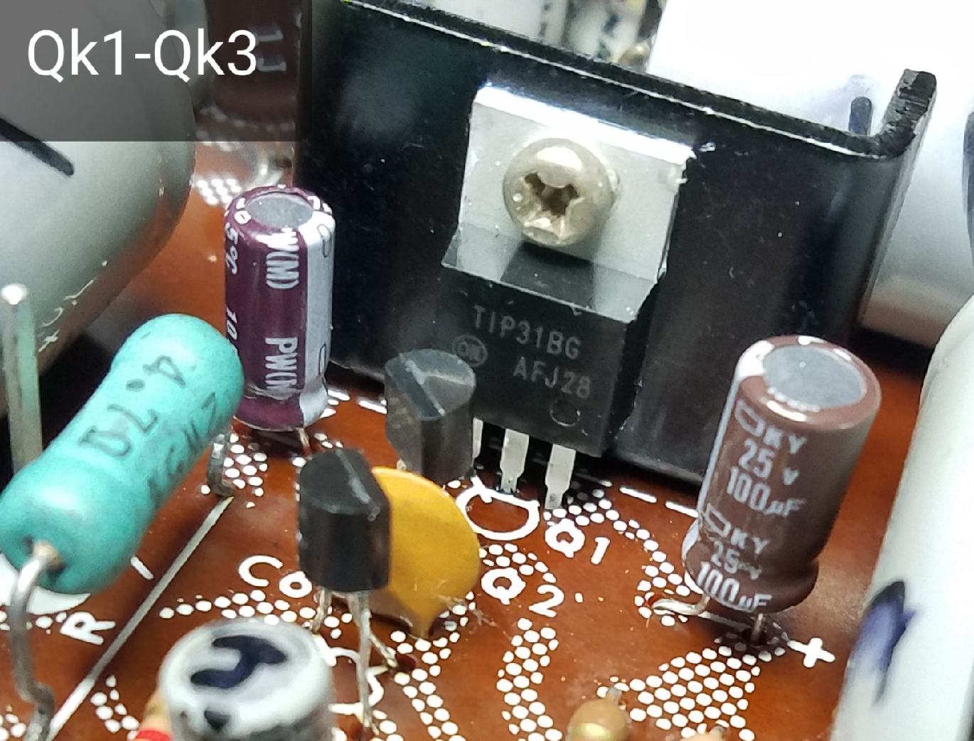
Desoldered transistors Q1-5, zener diode Dk1-3 and E caps. Tested resistors in circuit. Everything was to spec except for Q1, it was shorted C>E. I'm ignorant as to whether this failure was age related or possibly caused by some other component.
Replaced the following:
Qk1: 2SC789 (Y) > TIP31B
QK2-3: 2SC1000 (BL) > KSC1845
Qk4: 2SC1419 > MJE15032G
Qk5: 2SA755 > MJE15033G
I think this is ok for now to continue testing the unit with until the rest of the caps arrive. Will update.
___________
Full post:
I desoldered the wirewrapped pins to remove the whole board so I could take better pics.
Desoldered all testable components w/ FR-301 (1mm nozzle @ 350°C)
Cleaned glue, didn't cause any component damage.
The silkscreen has C19 polarity misprinted on this version. I checked @rickl 's KR9940 thread and his board was revised to fix this misprint. Note that C11 and C10 have extra spots drilled to fit a larger cap for some reason, maybe thats to fit a higher voltage for some reason?

Only caused partial damage to one pad due to a very crimped factory lead on one of the big axial caps, will repair this just for practice when new caps arrive.
Speaking of axials, I wish I could use a radial but I think it may look wonky/hacky based on how far the traces are apart? I think my most reasonable option are these Illinois Capacitors

With the board depopulated I thought it may be the best time to polish those header pins. I rolled up a kimwipe, dabbed a tiny spec of brasso on the middle and flossed each pin lightly. Rolled up a new wipe and flossed them with IPA. Then coated w/ Deoxit Gold.

Used LCR-T4 tester, all caps tested to spec in regards to ESR, capacitance and VLoss. I installed a few replacement Nichicon HE/PW & Chemicon KY I had in stock. The original caps were reinstalled so I can test further until order arrives.

Inspected Q1 (2SC789), it was shorted C>E. Not sure if this was just age related failure. Replaced with TIP31B.
Since Q1 was bad, I was advised to change out Q2-3 (2SC1000) were replaced with KSC1845. Wasn't sure if it was important to gain match but I found two that were 430 hFE.
Q4 (2SC1419) passed DMM test, hFE tested low around 70ish, wasn't sure if that was normal so replaced w/ MJE15032G:

Lastly, Q5 same situation as Q4. Replaced w/ MJE15033G:

With the board back together I may reinstall it and continue testing or may wait until I create a new order for replacing electrolytics. I'm also wondering if Qk1 could've been damaged by an unknown fault from one of the other two power supply boards, which makes me think I should check those first. Not sure, will update.
DBT being dim bulb tester???
yep. it will keep other stuff from blowing up.
you should probably create a KR-8840 thread so you don't thread cr*p on this one.
here is one example of a DBT.
Last edited:
I am very happy that i found this topic about the KR-9940. I am also a proud owner of the Europe model - the KR-9340,
which is the identical receiver.
It seems there is a small difference on how the power transistors are connected to the main amplifier board.
On the front cooling block directly behind the main amplifier board (counted from left to right) the connection of the power transistor is
Q5 - Q6 - Q1 - Q2
and on the rear cooling block
Q8 - Q7 - Q4 - Q3
compared to guy's 232 Kenwood KR-9940 Quad Amp Project postings.
If i compare the drawings between the KR - 9340 and the KR - 9940 of the main amplifier boards, there seems to be no difference at all.
Except for the wiring (regarding to the both service manuals) Q3 /Q4 are switched with Q5/Q6.
Also for adjusting the BIAS, i am not clear.
Isn't VRe4 for adjusting Q2, VRe3 for adjusting Q6, VRe2 for adjusting Q4 and finally VRe1 for adjusting Q8 in this case?
Maybe somebody can help me out here. Thank you very much in advance
which is the identical receiver.
It seems there is a small difference on how the power transistors are connected to the main amplifier board.
On the front cooling block directly behind the main amplifier board (counted from left to right) the connection of the power transistor is
Q5 - Q6 - Q1 - Q2
and on the rear cooling block
Q8 - Q7 - Q4 - Q3
compared to guy's 232 Kenwood KR-9940 Quad Amp Project postings.
If i compare the drawings between the KR - 9340 and the KR - 9940 of the main amplifier boards, there seems to be no difference at all.
Except for the wiring (regarding to the both service manuals) Q3 /Q4 are switched with Q5/Q6.
Also for adjusting the BIAS, i am not clear.
Isn't VRe4 for adjusting Q2, VRe3 for adjusting Q6, VRe2 for adjusting Q4 and finally VRe1 for adjusting Q8 in this case?
Maybe somebody can help me out here. Thank you very much in advance
Good morning everyone.....(sorry for my english, and my knowledge of electronics)..
I am new to this forums ..any forum as matter of fact so I don't know exactly they work , but I am passionate about vintage hifi and that old sound , and I was searching information regarding the Kenwood KR 9940 and I found this great post of guy232. Excellent work! I was wondering if anyone could help me with my 9940, which was given to me by a relative and I am trying to give it a new life.
I am not a fun of quad systems I would be using it as stereo probably ...in case I will repare it.
Ok too many words..........here is the problem :
I am trying to repair a Kenwood quad receiver KR9940.
It didn't power on at all, after first inspection I found a group of four power transistors all 4 on the same consecutive line and same matal dissipator (it sports eight transistors) NEC 2SD287 faulty which I replaced with four MJ15015 also the four matching wire wound 0.47 resistors where broken in half, and in the power supply board the two transistors 2SC1000 (QK2-QK3) faulty plus one other resistor and zener diode dk1, which I replaced with onother zener of unknown specifications.
After this first intervention I powered it up and the fuse R2 of 2 A blown plus the zener shorted and transistor QK2 broken. The Zener diode (DK1) YZ140 is of 14 V 500 mW as I could not find the exact one I used a 13 V instead. Previously I replaced the following faulty transistors QK1 2SC789, QK2 and QK3 2SC1000 with QK1 BD243c and QK2 Qkr with BC550 and BC 414. When I powered up the receiver smoke came from QK2 and the zener diode was shorted again. Is it possible that 1V for the Zener diode made the difference and blew the transistor? Also in this case as I cannot find the 14 V Zener diode could I possibly replaced it with two in series of 6.8 V each?
Anyhow I forgot to mention that previously , before the yz140 zener was shorted I did three attempts changing the transistor QK2 with (if i remember well) BC414...and 384 ...and all blown the transistors and the 2A FuSe.
Is it possible that the problem is somewhere else and not on the board in question?
Thank you very much for your help
I am new to this forums ..any forum as matter of fact so I don't know exactly they work , but I am passionate about vintage hifi and that old sound , and I was searching information regarding the Kenwood KR 9940 and I found this great post of guy232. Excellent work! I was wondering if anyone could help me with my 9940, which was given to me by a relative and I am trying to give it a new life.
I am not a fun of quad systems I would be using it as stereo probably ...in case I will repare it.
Ok too many words..........here is the problem :
I am trying to repair a Kenwood quad receiver KR9940.
It didn't power on at all, after first inspection I found a group of four power transistors all 4 on the same consecutive line and same matal dissipator (it sports eight transistors) NEC 2SD287 faulty which I replaced with four MJ15015 also the four matching wire wound 0.47 resistors where broken in half, and in the power supply board the two transistors 2SC1000 (QK2-QK3) faulty plus one other resistor and zener diode dk1, which I replaced with onother zener of unknown specifications.
After this first intervention I powered it up and the fuse R2 of 2 A blown plus the zener shorted and transistor QK2 broken. The Zener diode (DK1) YZ140 is of 14 V 500 mW as I could not find the exact one I used a 13 V instead. Previously I replaced the following faulty transistors QK1 2SC789, QK2 and QK3 2SC1000 with QK1 BD243c and QK2 Qkr with BC550 and BC 414. When I powered up the receiver smoke came from QK2 and the zener diode was shorted again. Is it possible that 1V for the Zener diode made the difference and blew the transistor? Also in this case as I cannot find the 14 V Zener diode could I possibly replaced it with two in series of 6.8 V each?
Anyhow I forgot to mention that previously , before the yz140 zener was shorted I did three attempts changing the transistor QK2 with (if i remember well) BC414...and 384 ...and all blown the transistors and the 2A FuSe.
Is it possible that the problem is somewhere else and not on the board in question?
Thank you very much for your help
Attachments


QK 2 and 3 are ksc1845 also always better with a higher voltage then lower on the diode I'm pretty sure also try a 1N5244B as replacement for YZ140Good morning everyone.....(sorry for my english, and my knowledge of electronics)..
I am new to this forums ..any forum as matter of fact so I don't know exactly they work , but I am passionate about vintage hifi and that old sound , and I was searching information regarding the Kenwood KR 9940 and I found this great post of guy232. Excellent work! I was wondering if anyone could help me with my 9940, which was given to me by a relative and I am trying to give it a new life.
I am not a fun of quad systems I would be using it as stereo probably ...in case I will repare it.
Ok too many words..........here is the problem :
I am trying to repair a Kenwood quad receiver KR9940.
It didn't power on at all, after first inspection I found a group of four power transistors all 4 on the same consecutive line and same matal dissipator (it sports eight transistors) NEC 2SD287 faulty which I replaced with four MJ15015 also the four matching wire wound 0.47 resistors where broken in half, and in the power supply board the two transistors 2SC1000 (QK2-QK3) faulty plus one other resistor and zener diode dk1, which I replaced with onother zener of unknown specifications.
After this first intervention I powered it up and the fuse R2 of 2 A blown plus the zener shorted and transistor QK2 broken. The Zener diode (DK1) YZ140 is of 14 V 500 mW as I could not find the exact one I used a 13 V instead. Previously I replaced the following faulty transistors QK1 2SC789, QK2 and QK3 2SC1000 with QK1 BD243c and QK2 Qkr with BC550 and BC 414. When I powered up the receiver smoke came from QK2 and the zener diode was shorted again. Is it possible that 1V for the Zener diode made the difference and blew the transistor? Also in this case as I cannot find the 14 V Zener diode could I possibly replaced it with two in series of 6.8 V each?
Anyhow I forgot to mention that previously , before the yz140 zener was shorted I did three attempts changing the transistor QK2 with (if i remember well) BC414...and 384 ...and all blown the transistors and the 2A FuSe.
Is it possible that the problem is somewhere else and not on the board in question?
Thank you very much for your help
Last edited:
and please use a DBT until you get it working. I had a difficult time getting this quad working and a DBT would keep from blowing up parts.
I said I'd never work on a quad receiver again (until I was asked to fix a QX-949A). I thought these were really difficult to work on and fix.
here is my thread that may help. I had to replace a lot of parts and some more than once.
I said I'd never work on a quad receiver again (until I was asked to fix a QX-949A). I thought these were really difficult to work on and fix.
here is my thread that may help. I had to replace a lot of parts and some more than once.

DBT Dim bulb tester..so you don't burn up components when testing..I believe if you type DBT into the search bar there's a schematic for making oneI forgot to mention that I found also R8 burned on the power supply board X00_1590 plus resistor R55 burned and transistor Q19 NEC 2SB536 shorted on the main amp board X07-1230
which I replaced with a 2SA968 ......
PS btw what is a DBT
Last edited:
Glad you got it going
Thanks Keven. the 9940 made me swear off fixing quads (for a year
 ).