• The move to the new server is done. There are some software and database maintenance updates in process. This has us passing the hat around to help out. We appreciate any donations. Seriously, even a dollar helps. The payment page may be found here - https://www.audiokarma.org/support.html

KLH 24 Crossover Anxiety

ace5000

New Member
I've been searching and reading here and the classic speaker forum until my eyes started bleeding. I need help.

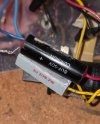
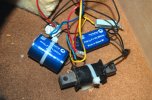
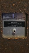
I picked up a clean pair of model 24s with the RCA plug. One of the SN's is A130322 if it helps. It has an 8uf cap, a 3 ohm resistor, and an inductor. Nothing else.

This is at least the 4th different configuration I have read about concerning the 22 and 24. Such as, (2) 4 ohms, an 8 and a 16, no resistor, with resistor, double cap, etc...

Question:
Why would I not just upgrade it to the 2nd order crossover used on the latest model 22? Its not being used with the 24 system, and the drivers are the same, yes? And, would it not sound better? Thx
 

Attachments

  • 20260708_213934.jpg
    20260708_213934.jpg
    72.1 KB · Views: 31
  • 20260708_215313.jpg
    20260708_215313.jpg
    74.4 KB · Views: 30
  • 20260708_222822.jpg
    20260708_222822.jpg
    100.6 KB · Views: 30
  • 20260708_213856.jpg
    20260708_213856.jpg
    75.9 KB · Views: 30
Register to hide this ad
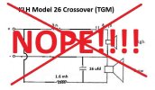
Looks like 22, 24 and 26 are basically the same speaker system. Apparently, they may also share the wandering crossover specs. I have a set of 26s and the only thing different between your 22s and my 26s appears to be the 16uf cap across the woofer. My Model 26 pair have the following circuit:

NOPE-KLHModel26-Crossover_2.jpg
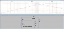
A really crude approximation in LTSpice shows the following crossover behavior:

KLHModel26-CrossoverSchematic-AsBuiltWithGraph.jpg

If the 16uf cap is deleted, the simulation looks like this:

KLHModel26-CrossoverSchematic-Without16ufCapWithGraph.jpg

Maybe you can see that the feed to the woofer above the crossover point doesn't drop off as much, or as quickly, when the 16uf cap is deleted. The actual frequency response of the woofer probably drops off fairly dramatically up there anyway so it may not be something that is that obvious.

Hope this helps.

Onward Through The Fog!
 

Attachments

  • KLHModel26-Crossover_2.jpg
    KLHModel26-Crossover_2.jpg
    18.6 KB · Views: 144
Last edited:
So foggy it's like London, but your input is appreciated.
To make matters even more complicated, I found the attached. It seems to be the latest update for the 22A. A 2nd order.
Im not good at schematics yet and need to figure it out. Nube question, is the inductor part of this?
 

Attachments

  • AISelect_20260709_033108_Samsung Browser.jpg
    AISelect_20260709_033108_Samsung Browser.jpg
    82.4 KB · Views: 24
The inductor is the squiggly line at the bottom of your drawing with "Blue" written to the right of it. No numerical value is given. The layout/order of parts is different between your drawing and mine but I believe the function is the same. Yours has the tweeter parts in reverse order and the woofer inductor is on the negative side rather than the positive side but I think it should result in the same outcome.

Anyone else see a problem?

Apologies for the cryptic appearance of the LTSpice representations. The signal generator/input is shown as a circle with + and - signs. The woofer (upper element R3) and tweeter (lower element R1) are shown as simple 8 ohm resistors.

I'd have to retrieve the 26s from storage to double check my drawing but I'm pretty sure it's factual.
 
Tj, Your crossover is based on the actual 22A, 2nd order design? If so, I should definitely copy yours, yes?
The inductor is the squiggly line at the bottom of your drawing with "Blue" written to the right of it. No numerical value is given. The layout/order of parts is different between your drawing and mine but I believe the function is the same. Yours has the tweeter parts in reverse order and the woofer inductor is on the negative side rather than the positive side but I think it should result in the same outcome.

Anyone else see a problem?

Apologies for the cryptic appearance of the LTSpice representations. The signal generator/input is shown as a circle with + and - signs. The woofer (upper element R3) and tweeter (lower element R1) are shown as simple 8 ohm resistors.

I'd have to retrieve the 26s from storage to double check my drawing but I'm pretty sure it's
 
If you mean "TG" ... My schematic drawing is what I found in a pair of KLH Model 26 speakers that appeared to be DEAD STOCK. I still have these speakers and thought, last time I listened to them, that they sounded pretty acceptable in spite of not recapping or doing ANYTHING to them. I didn't have them in heavy rotation or anything, just listened and then pulled the woofers and looked at the crossovers because I was having a hard time finding a believeable schematic online. I did run into some gutshots that provided a little insight but not a regular schemo.

From what I've seen the 26 has the same size cabinet as 22, 22A, 24 and 24II.
From what I've gathered from the online chaos, the 26 also uses the same drivers as 22, 22A, 24 and 24II.

I'd say go for it. You could probably do worse! Good Luck.
 
If you mean "TG" ... My schematic drawing is what I found in a pair of KLH Model 26 speakers that appeared to be DEAD STOCK. I still have these speakers and thought, last time I listened to them, that they sounded pretty acceptable in spite of not recapping or doing ANYTHING to them. I didn't have them in heavy rotation or anything, just listened and then pulled the woofers and looked at the crossovers because I was having a hard time finding a believeable schematic online. I did run into some gutshots that provided a little insight but not a regular schemo.

From what I've seen the 26 has the same size cabinet as 22, 22A, 24 and 24II.
From what I've gathered from the online chaos, the 26 also uses the same drivers as 22, 22A, 24 and 24II.

I'd say go for it. You could probably do worse! Good Luck.
TG! I hate to bother you further. Could you please share your drawing as it differs from the one I posted?
Thank you and I'll leave you alone after this. Im desperate haha. I will also need to figure out how to build it.
 
So foggy it's like London, but your input is appreciated.
To make matters even more complicated, I found the attached. It seems to be the latest update for the 22A. A 2nd order.
Im not good at schematics yet and need to figure it out. Nube question, is the inductor part of this?
The 22A x-over schematic matches that in my set of 24 series II speakers.
 
There ya go!
By the way, when I referred to a "drawing" I meant the schematic which I posted already near the top of my first response ...
Run it up the flagpole!
 
Darn, I missed it... Brain fog is a real thing! Ok, Im going in. Thx a million!
I'll report back when completed.
 
Just 2 more questions, I swear!

1. To16uf or not 16uf? That is the question. What's you opinion?

2. Should I replace the resistors?
Danka
 
My opinion is that you're probably not going to hear much difference by adding the 16uf cap, but why not try it? That's the fun part! It's just screws, particle board and your time ... I've found that dumping superglue in the area around each woofer screw hole while disassembled can help keep them from stripping out with repeated boogery. Just make sure to let it set up before reassembling.

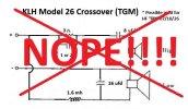
Another thing to try might be to "bypass" the resistor with a 1 or 2uf cap to increase the available upper top end if found to be deficient:
NOPE-KLHModel26-Crossover_3.jpg
I haven't listened to my 26s enough to notice if they may benefit from this. I remember them sounding pretty good as is.

Keep up the Good Work!
 

Attachments

  • KLHModel26-Crossover_3.jpg
    KLHModel26-Crossover_3.jpg
    22 KB · Views: 62
Last edited:
Excellent TG, thx. The glue tip is very helpful. Ive ordered the caps and resistors. Ive never laid out a crossover before. Its a challenge wrapping my nube head around the process.
 
you may want to consider maybe upgrading the 8uf and resistor to better parts, but leaving the values as they are. If you put in a 2nd order you will increase the phase shift over the original and may not end up with better sound. if there is nothing on the woofer circuit then the original designer may be letting it roll off naturally.
 
you may want to consider maybe upgrading the 8uf and resistor to better parts, but leaving the values as they are. If you put in a 2nd order you will increase the phase shift over the original and may not end up with better sound. if there is nothing on the woofer circuit then the original designer may be letting it roll off naturally.
I can't say I fully understand as Im the new super nube here, haha. My goal is to upgrade to the latest design, all things being equal. That would be the 22A (24 series 2) or 26 design - same speakers, same box. Am I incorrect in my thinking? Thx
 
Back
Top Bottom