• The move to the new server is done. There are some software and database maintenance updates in process. This has us passing the hat around to help out. We appreciate any donations. Seriously, even a dollar helps. The payment page may be found here - https://www.audiokarma.org/support.html

KLH 24 Crossover Anxiety

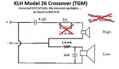
Hey Ace and Nikon, the picture of the Model 26 crossover parts in message #18 shows replaced, upgraded caps which is probably good. It also shows this crossover adheres to the hand drawn 22A schematic that Ace attached to message #3 and NOT the one that I provided. I'm going to have to go to storage and get my 26s to double-check my work. I probably screwed up ... I'll check back in after washing the egg off my face.
 
Hey Ace and Nikon, the picture of the Model 26 crossover parts in message #18 shows replaced, upgraded caps which is probably good. It also shows this crossover adheres to the hand drawn 22A schematic that Ace attached to message #3 and NOT the one that I provided. I'm going to have to go to storage and get my 26s to double-check my work. I probably screwed up ... I'll check back in after washing the egg off my face.
Good eye, thank you sir!
 
Question:
Why would I not just upgrade it to the 2nd order crossover used on the latest model 22? Its not being used with the 24 system, and the drivers are the same, yes? And, would it not sound better? Thx
I'm not a KLH expert but it's possible that although the speakers look the same, they may have slightly different specifications and have different crossover designs for a reason. If no model numbers are stamped on the woofers, testing them for T/S parameters would be the only way to know for sure if they are the same or different.
 
Certainly good points. I've gotta get an analysis setup going and book learnin' up to speed. There am oodles to grok!
 
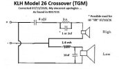
WHOOPS! I'm not sure what happened, other than the fact that I got old ... Turns out that my schematic that I posted initially and then modified slightly and posted again was in error. Again, functionally equivalent, but not factual.

BOOOOOO!

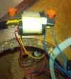
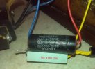
I retrieved my 26s from storage and pulled one apart. This thing is was PACKED TIGHT with fiberglass. Pics and corrected schematic below:

MyKLHModel26Pair_017231_1.JPGMyKLHModel26Pair_017231_4.JPGMyKLHModel26Pair_017231_5.JPGMyKLHModel26Pair_017231_8.JPG

There's a combo cap with both 8uf and 16uf elements, RED is common, BLUE is 16uf and PLAIN is 8uf. Anyway, here's the corrected schematic with my HF "Lift" mod suggestion added. Sorry for any needless confusion but it's par for the course these days ...

KLHModel26-Crossover_4-EDIT.jpg
The woofs are DRY AS A BONE so I'll have to give them a dose of RoyC's magic Butyl Sauce. Next, check the caps for expected drift.

 

Attachments

  • KLHModel26-Crossover_4.jpg
    KLHModel26-Crossover_4.jpg
    25.6 KB · Views: 79
Last edited:
I'm not a KLH expert but it's possible that although the speakers look the same, they may have slightly different specifications and have different crossover designs for a reason. If no model numbers are stamped on the woofers, testing them for T/S parameters would be the only way to know for sure if they are the same or different.
Understood. I'll have to look for any markings to make sure. Thank you for you're valued input.
 
KLH seems to have only used occasional date stamps and the odd magic marker "X" on their drivers to note polarity. No real driver model numbers other than sporadic magic marker notes on the woofer cones. Sometimes they are weights of the cones. You kinda have to get out the ruler, scale, and meters and familiarize yourself with them all. Malden has it right with the need to get measurements. There was a 3 page Service Bulletin published, part of which can be found online, that identified all the drivers that were current at the time but it's missing the page that seems to have contained the majority of them. The mystery continues ...

I checked the caps in the 26 above and, amazingly, found that they're still in the ballpark with 8uf = 9uf and 16uf = 18uf so I think I'll just leave them alone. ON WITH THE SHOW!
 
WHOOPS! I'm not sure what happened, other than the fact that I got old ... Turns out that my schematic that I posted initially and then modified slightly and posted again was in error. Again, functionally equivalent, but not factual.

BOOOOOO!

I retrieved my 26s from storage and pulled one apart. This thing is was PACKED TIGHT with fiberglass. Pics and corrected schematic below:

View attachment 3800920View attachment 3800921View attachment 3800922View attachment 3800923

There's a combo cap with both 8uf and 16uf elements, RED is common, BLUE is 16uf and PLAIN is 8uf. Anyway, here's the corrected schematic with my HF "Lift" mod suggestion added. Sorry for any needless confusion but it's par for the course these days ...

View attachment 3800927

The woofs are DRY AS A BONE so I'll have to give them a dose of RoyC's magic Butyl Sauce. Next, check the caps for expected drift.
TG, You are the man of the hour. Going into storage and checking out the crossover is going above and beyond. I once again thank you very sincerely. Im moving forward with this design, and will be back when completed. Tally Ho!
 
No good deed goes unpunished - poked a hole in woofer surround putting things back together ...
SHEESH! Thought I was done with that kind of screwup when I passed puberty. HA!
 
Yeah, not the end of the world. I think I've got it patched up with a piece of t-shirt cloth and RoyCs Butyl sealant. We'll see ...
 
you may want to consider maybe upgrading the 8uf and resistor to better parts, but leaving the values as they are. If you put in a 2nd order you will increase the phase shift over the original and may not end up with better sound. if there is nothing on the woofer circuit then the original designer may be letting it roll off naturally.
+1. At least give it the chance to show you what it can do with better part materials using stock values. Then, if you still don't like it, futz around with it but then there becomes a chance you make things sound worse. Just improving what's already there is guaranteed to make it sound better than it does right now.
 
+1. At least give it the chance to show you what it can do with better part materials using stock values. Then, if you still don't like it, futz around with it but then there becomes a chance you make things sound worse. Just improving what's already there is guaranteed to make it sound better than it does right now.
Pardon the delay in my response, as I've been moving. I get your point. However, I've already ordered parts. I guess I can always subtract some if they sound like $hit. I've also ordered the Royc goop for the surrounds. I will report back. Thanks.
 
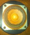
As I already had my Model 26s at the house I worked on them a bit. I noticed that the tweeters were riding on the inner scrim of the grille cloth ... that can't be good. Actually enough to get stuck to the cloth a little. See below:

KIMG1315.JPGMyKLHModel26Pair_017231_2.JPG

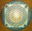
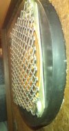
I decided to fashion a screen that rides a little bit proud on some soft plastic spacers:

KIMG1308.JPGKIMG1314.JPG

Of course, now it causes the grille cloth to "pooch out" a little bit in that spot but not really enough to be distracting ... to me, anyway. I can't imagine this metal screen changes the sound in any appreciable way. One side benefit is that I was able to restore the poked in dust cover using alcohol and a vacuum cleaner with a reducer hose. People seem to LOVE messing with those things and the fact that it rides so close to the grille cloth doesn't help. I was also able to seal the plastic can to the baffle board with some small diameter rope caulk and this seemed to help the woofer back pressure. These things actually sound pretty fine!
 
As I already had my Model 26s at the house I worked on them a bit. I noticed that the tweeters were riding on the inner scrim of the grille cloth ... that can't be good. Actually enough to get stuck to the cloth a little. See below:

View attachment 3804502View attachment 3804503

I decided to fashion a screen that rides a little bit proud on some soft plastic spacers:

View attachment 3804504View attachment 3804505

Of course, now it causes the grille cloth to "pooch out" a little bit in that spot but not really enough to be distracting ... to me, anyway. I can't imagine this metal screen changes the sound in any appreciable way. One side benefit is that I was able to restore the poked in dust cover using alcohol and a vacuum cleaner with a reducer hose. People seem to LOVE messing with those things and the fact that it rides so close to the grille cloth doesn't help. I was also able to seal the plastic can to the baffle board with some small diameter rope caulk and this seemed to help the woofer back pressure. These things actually sound pretty fine!
That looks great. Very resourceful.
 
Lieutenant Columbo has just one more question: As long as Im building a new crossover, why not replace the inductor?
I've read it's a 1.6mh, is this correct? Also, is this a stupid idea and just use the original?
 
In addition to my question above, I received this message from a friend helping me out, "this latest schematic has the coil on the negative lead going to the woofer. Conventional practice is to put such things on the positive side."

What is our reaction to this comment?
 
#37 - No, leave the inductor if it's functioning. Nothing to be gained. Same with resistors, unless they are burned/open. These parts don't suffer from age related failure like electrolytic capacitors do.
#38 - That's the way I drew it initially, probably because that's conventional practice but that's NOT how KLH did it. The homemade pencil drawing you posted in #3 was correct and my CORRECTED schematic is factual (with the exception of the suggested "HF Lift" mod).
 
Back
Top Bottom