• The move to the new server is done. There are some software and database maintenance updates in process. This has us passing the hat around to help out. We appreciate any donations. Seriously, even a dollar helps. The payment page may be found here - https://www.audiokarma.org/support.html

KT88, (ect) Single ended amp, SEUL

With the original schematic and using KT88's you can scale to say 500v without issues.
(that is as long as your supply caps aren't at or over voltage that you used)

Just check plate voltage on drivers, may want to lower cathode resistor and adjust R5.
(also watch current on the outputs, may want to up cathode resistors to say 560ohm)

450v should work well with 6L6GC's or EL34's, curious what voltage do you have there?

When plugged directly into the mains; my B+ off the last cap was about 480v with tunes playin' for whatever that's worth. I haven't checked voltage at the plate, probably be a couple days before I have a chance to
 
Last edited by a moderator:
That 480v would be good for KT88's, you'd want to check plate dissipation for
all tubes though, ecspecially 6L6GC and or EL34 at that voltage, even the KT88. :thmbsp:
 
Last edited:
If you mean spice simulation, I use Multisim. (and MS Paint for schematics) ;)

---

But to be clear it does not design anything, you do the thinking an designing in your
head, then if you want to make some voltage measurements before you build it that
is where spice comes in handy. (also you can take a screen shot for the schematic)

This design was refined over about a 2 year period, with real world testing an seeing
in spice what that testing was telling us an some things to try before testing further. :)
(in other-words, spice in combination with real world testing and designing is used)
 
This amp is quite similar to my RH88 proposed for the first time in 2005 to a few friends - the amp being part of the 2nd generation of RH amps.
Still, as 2nd gen it is far simpler than the one proposed here... I believe the schematics can be found on the net.
Anyone interested?
 
Alex only thing resembling your amps is that I'm using schade style feedback.

Not a new concept, and the 6EJ7 with higher transcon and this well adjusted
circuit is an exceptionally fine driver, I've been running schade style feedback
in single ended amps for quite some time, and like you I prefer it over "global".

Other then that our amps are setup quite different, from different driver tube
to the LED biasing there really isn't much they actually have in common there.

I would suggest if you'd like to promote Your DIY designs start an new thread.
 
Not sure if anyone is still listening on this thread...but here it goes:

I'm thinking I'm going to build this amp after I finish my current projects (and my wallet recovers).

Questions:

  1. I'm going to build it to use the 6L6. Is there anything specific I need to be aware of when using the 6L6? About how much power output should I expect when using this tube?
  2. Why cathode bias and not fixed bias?
  3. Why have the LED in the cathode circuit of the 6EJ7? Would a regular resistor work just as well? Is the LED offering some sort of sonic or other advantage?
  4. Interesting feedback topology. Has anyone looked at a square wave reproduction on this amp? Is there overshoot and/or ringing on the transitions that should be dealt with? Do we care about such things on single ended amps?

Can't wait to build my first single ended amp.
 
6L6GC would be just fine, if the standard 6L6 keep voltage to 400v or less.

Cathode bias is simpler, an with the supply here fixed isn't "needed" on this.

The LED acts as a resistor with no bypass cap needed to not add feedback.

The LED and Resistor on the cathode along with the feedback resistor have
been tweaked and adjusted through a lot of testing both with an scope and
distortion analyzer to give best distortion/power and harmonic content so it
gets good power, lower distortion and still be dominated by Even Harmonics.
(no issue with square wave an overshoot and/or ringing on the scope)

The amp should produce between 9-14w depending voltage and tubes used.
 
Last edited:
Edcor CXSE25-4-5K ?

Hello,

I have finally bought parts to this project (took 2-3 years!)

I bought Edcor CXSE25-4-5K output transformers, but now I am a little bit uncertain if I should use Edcor CXSE25-8-5K.

How is it with this output impedance? Is this 4 ohm transformer ok for this amp, and what effect this impedance has to sound?
 
Depends on your speakers ohms spec. Anyway it might not hurt too much if your speakers are 8 ohms as though out the freq. response they probably have low dips and ranges.

Also tube amps aren't too fussy, unlike some SS.
 
Last edited:
Kegger is building me this amp as we speak. Seeing this post just adds to the anticipation. I can't wait!
 
Hello,

I have finally bought parts to this project (took 2-3 years!)

I bought Edcor CXSE25-4-5K output transformers, but now I am a little bit uncertain if I should use Edcor CXSE25-8-5K.

How is it with this output impedance? Is this 4 ohm transformer ok for this amp, and what effect this impedance has to sound?

Depends on your speakers but if you have 8 ohm speakers it will sound better with 8 ohm output transformers. I just tried this with my 8 ohm speakers. I have 2 SE amps in rotation, one with 4 ohm tap and one with 8 ohm tap both Edcors, the 8 ohm (gxse) sounds better than the 4 ohm cxse on the 8 ohm speakers. But thats MY speakers, ymmv. I have both 4 & 8 ohm speakers & 8 ohm speakers very inefficient 86db that sounds the same with either amp. The VERY efficient speakers 105db (8ohms) sound better with the 8 ohm tap my other speakers Infinity QLSIII (4ohm or less) sounds better with the 4 ohm tap single ended and sounds better with the 8 ohm tap with my push pull amp. My point, really depends, experiment and try some different speakers go to a friends house and try his/her speakers ... you get the idea.

If Kegger is reading this thread I'm wondering about a little cathode feedback with this amp and the GXSE transformers, can we try some? Probably not needed with the big CXSE transformers.

Cheers,
Bob
 
My guess with using the 4 ohm OT with an 8 ohm speakers is that you'll reflect a higher impedance to the tube, which should lower distortion and power output.

I think you'll be fine, especially if you have efficient speakers.
 
My guess with using the 4 ohm OT with an 8 ohm speakers is that you'll reflect a higher impedance to the tube, which should lower distortion and power output.

I think you'll be fine, especially if you have efficient speakers.

I'd go with this.
 
The other thing is that Edcor rates the CXSE at 20 to 20KHz and the GXSE at 40 to 18KHz. It may not make a difference but they're not the same transformers aside from the impedances and size.
 
Hi guys

Thanks a lot kegger for this nice kt88 design, I decided to build this amp:-)

What I got so far:
- James Output transformers (6123) (brought from a recent visit in Taipeh)
- Ordered a 350-0-350V 200mA and 5V 5A audio grade toroidal transformer in Germany
- A nice (french) SMPS with 6.3A output DC with 10 Amperes
- A good friend with a laser who will cut the 2mm plate out of stainless steel

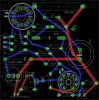
My question: I am not really experienced nor talented with point-to-point design (tried it a long time ago, worked but was ugly), and after the build of two amps of Pete Millett and after reading a lot about other guys who did PCB boards for tube amps, I thought I give it a try.
So far I just did lots of digital boards with 2-4 layers and nice parallel/45° traces. This time I tried another approach by trying to avoid parallel lines, even did no 45° angles, tried with thick traces and as much distance as possible. furthermore I tried to keep the signal lines short and away from the high power lines.
Not really sure yet if I will put a ground plane on the top (what you see on the board in red is the (actual) ground...

It would be very nice to have the opinion of some more experienced analogue/audio designers about that PCB...

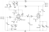
I will attach the images, but also the actual Eagle files.


Best regards from Geneva
Christoph
 

Attachments

  • KT88_SET_KEGGER_S.png
    KT88_SET_KEGGER_S.png
    15.2 KB · Views: 441
  • KT88_SET_KEGGER_BRD.png
    KT88_SET_KEGGER_BRD.png
    88.8 KB · Views: 356
  • KT88_SET amp by Kegger.zip
    KT88_SET amp by Kegger.zip
    80.2 KB · Views: 169
The one in this thread is the latest and the most time spent with the design here.
(and this design is still getting updates and tweaks)

The other is a good amp as well, just a different driver that's more known for some.
 
Kt88

One minor question of the schematics.
What means CC in 510R CC ? (6EJ7 resistors) ?

I am just assembling parts to the plate.

3tct.jpg
 
Back
Top Bottom