• The move to the new server is done. There are some software and database maintenance updates in process. This has us passing the hat around to help out. We appreciate any donations. Seriously, even a dollar helps. The payment page may be found here - https://www.audiokarma.org/support.html

Kyocera A-910 Restoration & Information Thread

Left amplifier section cont’d:

After quite a bit of time and effort, the left hand amplifier module is ready to be reinstalled into the chassis. I spent around 8 hours restoring this module alone. It goes to show that this job is truly a labor of love. Specialized care like this is very hard to find and is certainly not cheap if you were to have someone else do it. Attention to detail is key here.

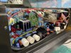
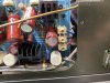
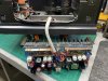
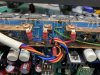
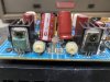
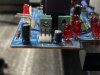
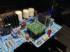
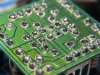
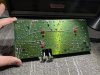
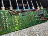
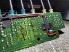
Top and bottom view of the left hand module after tons of careful servicing. Everything was done to this board. Removing all corrosive glue and related corrosion damage, recap with Panasonic FC electrolytics, reflow and deflux the board, remount all TO-220 style transistors on new thermal interfaces, rewiring all of the unnecessarily long hookup wire, replacing many cracked and discolored ceramic bypass capacitors with better parts, polishing bus bar contact points, replacing many resistors and diodes, as well as reworking the input differential board. All of this has to be repeated on the right hand channel as well.
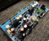
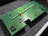
photo_2022-01-29_16-32-18.jpg photo_2022-01-29_16-32-20.jpg


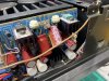
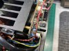
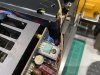
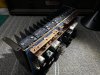
After a careful inspection of the board, it is ready to be remounted to the heat sink and be reinstalled into the 910. After attaching the board to the heat sink, all of the MT-200 outputs have to be resoldered. I remounted all of the MT-200's on new silicone thermal interfaces as the old thermal grease was as dry as a bone
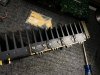
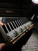
photo_2022-01-29_16-32-22.jpg photo_2022-01-29_16-32-23.jpg

And here is the final product ready to be reinstalled!
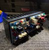
photo_2022-01-29_16-39-08.jpg photo_2022-01-29_16-39-10.jpg
 
Left amplifier section cont’d:

I successfully remounted the left hand amplifier module into the A-910 chassis this past weekend and started testing.

Bringing the amplifier up on a variac, I monitored rail voltages, bias, and offset. After letting the amplifier settle, the offset stabilized to a very low ~2mV, and the rail voltages were spot on +/- 76v.

7B6C8F12-4B9B-47EF-8827-00DDB1834E03.jpeg 1D6D241E-5D93-4F29-862F-3BECF7C2B9A1.jpeg

The DC offset is non adjustable, so you are relying on the close matching of the input differential and stability of the rest of the circuit in order to achieve a low center voltage. +/- 2mV is spectacular.

After letting the amplifier stabilize, I did a few power tests while loading the amplifier into 8 ohms. Testing the newly rebuilt left hand channel, I achieved an impressive 200 watt output. This is 50 watts more than what the service manual specifies. I assume I would achieve an output closer to 150W while driving both channels simultaneously.

Testing the square wave performance also yielded an impressive result. Take a look at this 1KHz square wave, when loaded into 8 ohms…

7304F06D-9F39-4C24-8609-45B461F98271.jpeg

Now that the left hand channel is done, I will be moving to the right channel and repeating these same steps. I’ll keep this thread updated as I continue the process.

Thanks for reading along!
 
Right amplifier section:

I started work on the right amplifier section, starting by removing the amplifier module from the chassis and taking some detailed photos of what I’m up against…

It seems that someone has been working on this module in the past. I see a few solder joints that have been touched up, a single capacitor that has been replaced, and some messy thermal compound randomly spattered about. Someone also lifted a few traces for the output transistors that will have to be repaired…

Luckily, there isn’t any other damage, and this module will require the same attention that the left hand module received.

D2C1D3B8-AEAC-4E71-9DCB-E9CCA4880376.jpeg FE5E0BF7-8F2C-4A2C-8C64-406E15C16A43.jpeg F727A2A9-AD0F-40B1-9750-3023A38F2937.jpeg 15012441-602E-423F-9EB8-F5CD26F66A4C.jpeg 1F52730B-DA84-4241-B0BA-ECCC1B8050A9.jpeg 68114585-6A04-4AD7-9D6A-5574DD927E63.jpeg 4FA818CD-3B51-4AE9-96F7-27A8523E73B6.jpeg 98C24213-DDCD-4944-9440-515374353860.jpeg 64797C89-3DE1-4B9C-8988-FB3733AD49F6.jpeg A081EBCB-3C32-4778-85C8-7337EC0F3916.jpeg

I will likely start work on this module tomorrow and will follow up in this thread shortly thereafter. Stay tuned!
 
After a long hiatus, I finally managed to finish the restoration of this beautiful Kyocera A-910. I will continue this thread where I left off, which was the disassembly and rebuild of the right hand amplifier module.

As most of the work is identical to the left hand side, I won’t go into as much detail as I did previously. All of the same processes and techniques were used, but I did change a few things here and there including mounting of capacitors onto the top side of the board, where they were originally bodged to the bottom.

Right amplifier section cont’d:

As stated before the work done to the right channel is basically identical to the left. Recap, reflow, glue removal, rewiring the point-to-point connections, deflux, and test.

The only difference here is that I replace the large filter capacitors on the board that I decided to leave on the other board. One of the leads of the capacitors had snapped off during removal, which made me rethink my decision to leave the old ones in place. I decided to replace them all, and with this method, I’d have to take the left-hand module back out to do this as well. Other than that, I decided to drill holes in the top of the board to allow for through-hole mounting of some capacitors which were bodged onto the bottom of the board at the factory.

Here is the change that I made. I removed the old capacitors, drilled holes through the board, and mounted them as shown:

7D387736-B7F0-4E74-A986-22F5240C8434.jpeg 9ECE5CAE-54F2-4784-8ED0-AF20D41AEBC3.jpeg 249617B7-DBAC-403A-8B1A-DFBB4987DC38.jpeg

Just as before, I also completely reflowed and defluxed the main differential input board.

FA501BAE-BEAD-43D2-9585-15EEDDE23DFC.jpeg B01E635B-7FCE-420F-8A65-B748B3E1456C.jpeg E0AC071B-9C58-4376-8AF3-ED977DE4468E.jpeg 64ED0D2C-F69D-4C69-8AFB-74445C1CC7D4.jpeg

After finishing the rest of the process, the right hand module is ready to be reinstalled.

B0519123-ADD6-4D48-8982-BFBB54CFBF3B.jpeg 9B3868DA-6C39-417B-9E8F-E5A8191D4A51.jpeg
 
Last edited:
Power supply filtering section:

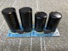
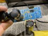
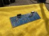
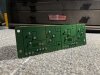
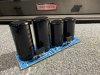
After finishing the right hand amplifier module, I moved onto the small circuit board used for four of the large filter capacitors. This board was challenging to remove, as all of the wires were soldered directly to it and glued into place. This board required the same processes as before, which included a complete re-flow, removal of corrosive glue, and a thorough deflux. I tested all of the capacitors on my Sencore LC102 capacitor analyzer, and they measured perfectly within spec and did not need to be replaced. All I needed to do to them was to remove the glue that was adhered to their base.

D0D2369F-663E-4F7E-ACBC-6FA17C6485F3.jpeg 62558966-D46B-40D1-A4D9-7A17BE7D6249.jpeg 3ABDD702-0A44-49CD-968E-EE2BC59B0BF9.jpeg F9E22812-C72D-4D61-B1FB-D1873BA47294.jpeg E3AC3D04-FA62-4499-A2EA-661B93F7EA68.jpeg 8A21FB51-686D-4369-B8E8-E3D68C56EB9B.jpeg 86E8F19F-505B-443B-BC7F-4C7E090E4448.jpeg F542C827-05DE-4146-A1E9-6094341D7EE5.jpeg

Although this job was simple, it did take quite a while to remove all of the glue from the board and capacitors.
 
Moving coil headamp and power supply section:

Moving toward the front section of the amplifier, I decided to start with the moving coil phono stage and power supply. The phono stage and the matching power supply are mounted directly to the front sub panel behind the face plate. They are configured in a strange way which makes removal and servicing tricky. Once removed, I was able to gain access to the circuit boards for service.

Same story with these boards. Cold solder joints, lots of nasty flux, and old capacitors.
After reworking them, they were moved to the side in order to gain access to deeper parts of the front section of the amplifier.


MC Stage before rework:
9A412AE8-996F-47EB-A72F-9D5E959C54AB.jpeg 6B67C0EC-43A1-48D0-8E5D-543C9ACFF214.jpeg

MC stage power supply before rework:
33742BF8-9373-4AB9-B9A7-06C40D0E7F13.jpeg 46A7C2FC-58FF-4425-B45B-CB363DECC676.jpeg

MC stage and power supply after rework:
A6759565-6156-4506-B5B2-0A56950E5DB9.jpeg 2BF3E1A0-9224-4744-9F4A-58D22ACB63D4.jpeg 4CE94294-FA27-4B10-BB77-CCBAA55D62C5.jpeg


Last edited:
Front assembly section:

Digging deeper into the front section of the A-910, there are multiple boards that need to be reworked. Many of the switches on the front panel control push rods that reach to the back EQ / phono section of the amplifier. This enables utilization of a much shorter signal path so signal wires don’t have to be routed to and from the front panel. This lowers noise floor as well as reduces the complexity of the amplifier. The circuit boards still have to be reworked, as much of the soldering is pretty poor.

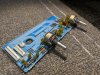
Here are a couple of boards that were removed and reworked during the disassembly of the front panel. As before, all that was required was a rework and a deflux process.

9E913FA9-7E88-4D77-AC71-A51DC808DE98.jpeg 38B35BFF-2B87-453A-BB8D-41F1B14BB4B1.jpeg 02E74AD1-F9D2-47C4-993C-40801BE3F9BE.jpeg 2EA7612B-9474-48B8-BC9F-787A632B602B.jpeg 3EA086E9-7F61-4931-AEE0-3759157EE07B.jpeg 694E1982-9CCE-47EA-82AA-45A72C15E9F1.jpeg 3641DF54-D5EE-4659-9DA9-7774CE127987.jpeg F2160D6C-EF48-4A88-B80C-02D9715C7AE3.jpeg

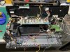
Here’s a couple of pictures of the front section during disassembly. Lots of wires going to different parts of the amplifier. Not many signal wires though…

68B9052C-19F6-4D8E-AD8F-5CB7C59437CD.jpeg EA67D241-12B5-46AC-9355-04DB687BACF6.jpeg
 
Last edited:
Front assembly section cont’d:

The final board which houses the push button assembly was the hardest to access. It is sandwiched between the front subchassis and the CCR base. Lots of PCB’s and wiring stacked on top which made removal a nightmare. I needed to take lots of photos showing where each wire and connector went. There is a lot that can be mixed up if you’re not careful to label or take pictures!

3BCBC622-3587-40BD-972D-B04223AE6207.jpeg 628F2B03-DFD5-4FCC-BF5A-DCA6780BD777.jpeg 0CB808CC-0CDC-44B4-A86E-373DE1EAE007.jpeg

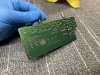
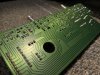
The PCB for that houses these buttons needed quite a bit of work. Not only did it have questionable solder quality, but it had quite a bit of corrosive glue holding down wires to the bottom side of the board. The glue had started corroding the wiring, so I opted to change the wires out with new.

BDE871ED-C65C-4C87-B840-473B24DD26AE.jpeg FD1FE846-793D-41C8-9067-D9C67668E719.jpeg

After reworking the board, the finished product looks better than new!

1892B68D-FDDA-4059-B29F-572A6E4D4836.jpeg


While I had the volume potentiometer out (Alps RK40), I decided to open it up for a cleaning and lubrication treatment. This particular RK40 was physically “grainy” when turned, so a cleaning and lubrication helped that issue out perfectly.

66B5B7D0-D8E9-4B59-800D-6910DF66CB48.jpeg

I spent about an hour reassembling the front section of the amplifier, making sure to get everything connected back to it’s proper location. With this many wires to connect, one wrong move could send a ball of smoke up from the depths of the amplifier!

CA859C63-EE88-4060-8310-DCD93573DCC3.jpeg DB7C9CF8-3D05-4C5F-8F7E-4CE531396F51.jpeg 5CC55767-B117-48CF-8CA5-079A670ED15D.jpeg
 
Wow! Outstanding rebuild! That's professional work, 100%, all the way! :thumbsup::thumbsup::thumbsup::thumbsup:
Thank you! It is very encouraging to have people compliment my work. I dedicate myself to a high level of care and craftsmanship, often times spending time on things most people would generally overlook. By the way, I do offer my services to outside parties, although as I have a full time job, audio restoration work has been mostly a hobby for me since graduating school. While I will work on others’ gear, it is generally a slow process. PM me if you would like to arrange service for your 77ES. Thanks again!

Connor
 
Power supply section cont'd:

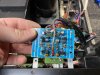
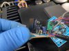
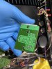
After recapping the power supply board, removing the corrosive glue, and repairing the relay, I decided to reflow and deflux the entire board.
Reflowing and defluxing PCBs is also another very time consuming process, especially when done right. Many people often times overlook many questionable solder joints, and not to mention, fail to deflux the board after working on it. I like to deflux circuit boards for a few reasons.

1: Defluxing makes it very easy to inspect your work and make sure there aren't any solder bridges or broken traces. With a thick coating of flux on a circuit board, it makes it almost impossible to be able to get a good look at all of the joints and connections. Once it's defluxed, you are able to see every detail.

2: If your flux is acidic, it's best to remove it from the PCB entirely. Most flux used today is non-acidic, so it won't attack or corrode traces. But I have seen my fair share of damage caused by acidic flux left on circuit boards, so I make it a habit to remove it all. It doesn't hurt.

3. It makes your work look much better. When I open an amplifier that's previously been worked on, I usually see gobs of flux coating the circuit boards. This tells me the previous person to work on the piece of equipment didn't really care about the final product, or was rushing to get the job done. When I finish soldering, I always like to deflux, even if it adds extra time to the job.

I use an acid brush to apply flux to boards I am reflowing. I also add solder to any joint that needs it. Adding flux to every joint makes the process go much faster vs relying on the flux in the solder you are applying. I get shiny joints that look great every time this way.

View attachment 2445828 View attachment 2445829 View attachment 2445830

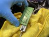
The last thing to do was to remount the TO-220 transistor on a new silicone thermal interface. I noticed that all of the thermal compound in this A-910 was dry as a bone, so replacing the mica and grease with silicone pads is what I will be doing with every transistor. There is a never ending debate about whether or not silicone pads are as good as the standard mica and grease. My view is that if you use high quality thin silicone insulators, they will be very close in terms of thermal transfer when compared to mica and grease. The efficiency of mica and grease also depends heavily on how much compound you use, and how thick your mica insulator is. I use silicone in almost all of my restorations and projects, and have never had a single issue. Even when used in class A driver and output sections that get very hot. Silicone pads are also much easier to install, and in turn result in a much cleaner end result.

View attachment 2445832 View attachment 2445833 View attachment 2445834

The final result is great. After reworking the PCB and installing it back into the chassis, I redid the wiring and made it look much cleaner than stock. This will make it much easier to remove the board in the future if need be. I'm really happy with how it came out, but this is only one small piece in the puzzle that is the A-910. I have since started working on the amplifier sections, and they are proving to be much trickier to work on as they are filled with corrosive glue. I will update this tread as I get closer to finishing them and I will be sure to take many detailed photos for all of you who are interested. Stay tuned!

View attachment 2445831 View attachment 2445836
Very impressive.What do you use to remove-deflux the PCBs.
 
Wow, very nice work Connor, I really enjoy seeing people do such meticulous work!

I almost bought a Keyocera turntable back when it came out but had trouble
finding a dealer close by. A few months ago one came up locally and I bought it,
the guy said I have the Keyocera receiver also do you want it, no charge! I've
not dug into it as I have too many projects!
 
Thanks for the tip. Also, you mentioned a product to use on my amp to cleanup the face surfaces. Can you remind me what it was please?

Thanks!
 
Thanks Glenn. I use 99% isopropyl alcohol and a toothbrush.

Yes, and if you keep it handy as you solder, it comes off much easier say 30 seconds
after you solder, so keep some handy and Q-tips or whatever you prefer for removal.
Then final cleanup with a brush. This is a tip a few friends use.
 
Thanks for the tip. Also, you mentioned a product to use on my amp to cleanup the face surfaces. Can you remind me what it was please?

Thanks!
Hi Glenn, I recommended Simichrome. It works great on all sorts of metal finishes. Use a small amount on a clean microfiber towel and use light pressure.

Your Victor amplifier has a satin finish to it and not standard brushed aluminum. One trick I use to clean finishes like that is to use “LA’s Totally Awesome” degreaser. You can get it at the dollar store. Coat the faceplate and let it sit for about 30 seconds. Rub it in with your fingers (yes, really) and then wipe it off with a clean microfiber towel. I would personally try this before using Simichrome. I’ve had great results and have been able to remove years of nicotine stains and grime with only one cleaning process. Let me know how it goes!

6FD885A8-5F59-4819-91E7-F0BA61F819CE.jpeg F8C7D3D5-1A44-4AC6-B2D8-53BE67697452.jpeg
 
Hi Glenn, I recommended Simichrome. It works great on all sorts of metal finishes. Use a small amount on a clean microfiber towel and use light pressure.

Your Victor amplifier has a satin finish to it and not standard brushed aluminum. One trick I use to clean finishes like that is to use “LA’s Totally Awesome” degreaser. You can get it at the dollar store. Coat the faceplate and let it sit for about 30 seconds. Rub it in with your fingers (yes, really) and then wipe it off with a clean microfiber towel. I would personally try this before using Simichrome. I’ve had great results and have been able to remove years of nicotine stains and grime with only one cleaning process. Let me know how it goes!

View attachment 2531561 View attachment 2531562
Thanks Connor, much appreciated! At some point, I'll either repaint the case, or make a nice wood case with beautiful veneer.
 
Back
Top Bottom