• The move to the new server is done. There are some software and database maintenance updates in process. This has us passing the hat around to help out. We appreciate any donations. Seriously, even a dollar helps. The payment page may be found here - https://www.audiokarma.org/support.html

Kyocera A-910 Restoration & Information Thread

Revisiting the dead but not forgotten A-910 thread...

After a long hiatus, I finally have time to update this thread with at least a couple of posts... The A-910 has been done for a few months now, other than some gremlins in the rebuilt phono stage. I'll leave that debacle for later though. For now, I want to update you all with some of the other work I accomplished during the radio silence.

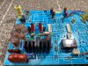
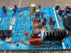
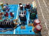
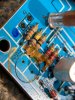
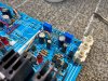
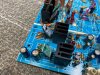
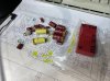
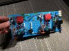
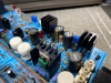
First off, I would like to add a few more photos of the right and left hand amplifier sections. During overhaul of the right channel, a lead from one of the original 470uf Elna capacitors had broken off, necessitating it's replacement. (These are the large red capacitors located on the amplifier boards which I was planning on leaving in place.)

Because only one had to be replaced, I couldn't replace it without also swapping the rest out... So I changed them all, even on the left hand channel which I had just installed into the chassis. Oh well...

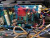
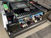
Attached are some of the photos of both modules completed with the new Nichicon Muse 470uf Capacitors:

upload_2022-7-13_21-25-56.png upload_2022-7-13_21-26-14.png upload_2022-7-13_21-26-32.png 1.jpg

2.jpg


At this point, I was very excited to finish what I thought was the most meticulous part of this restoration. Boy was I wrong! :rflmao:
 
Last edited:
Rear section:

Up until this point, everything had been going rather well. No major hiccups, no broken components, and no smoke!
Other than the tedious process of removing, reworking, and reinstalling the front section, it was smooth sailing... That was until I took a look at what I was up against in the rear section of the amplifier. Not fun!!!

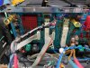
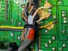
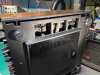
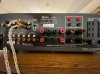
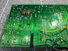
Just take a look at all of the wires leading to the rear section of this amplifier! Not to mention the fact that many of them are simply bodged onto the back of the phono and tone amplifier PCB, held on with corrosive glue!

rear5.jpg rear2.jpg rear7.jpg
rear3.jpg rear4.jpg rear9.jpg rear10.jpg

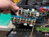
To spare the gory details, I managed to remove both the I/O circuit board which houses most of the amplifiers line and phono inputs & outputs, as well the phono and tone stage board. This was an extremely tricky process for many reasons, not the least of which being the fact that there is simply next to zero slack on any of the wiring in the rear section of this amplifier. Pair that with the fact that many of the wires are directly soldered, but also because I had to scrape a metric ton of glue to even access the solder joints of said wires. Also, because this amplifier utilizes push-pull control cable driven switches, I had to completely desolder the switch assemblies from the phono board; each assembly containing 40-50 individual solder joints! This one process makes the purchase of my Hakko FR-301 desoldering gun worth every penny.

rear13.jpg rear12.jpg rear11.jpg
 
Rear I/O section:

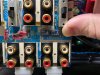
Upon removal of the circuit boards from the back side of the A-910, many faults were found. Mostly standard old-amp things such as tired soldering and corrosive glue. The I/O board, as well as the speaker terminal board cleaned up nicely. I also managed to polish the RCA terminals and deflux both boards. After tidying them up, the results speak for themselves! :)

g1.jpg g2.jpg g3.jpg g4.jpg
g5.jpg g6.jpg g7.jpg
 
Rear phono / EQ section:

Here we are. The final piece of the Kyocera A-910 jigsaw puzzle. After countless swear words and drops of sweat, I managed to free the phono section from the bowels of the 910.
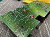
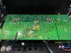
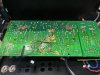
This board was bad. Real bad. Lots of high current devices which had vaporized solder joints, buckets of corrosive glue, and a slathering of baked on flux reside for good measure. I had my work cut out for me on this one.

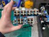
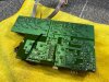
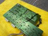
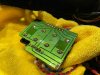
To start, I gathered a few photos of the condition that this PCB was in. Certainly not pretty, but totally serviceable.
I spent the good part of an hour removing components in order to gain access to the glue that needed to be taken care of; not to mention having to very carefully scrape glue from the solder mask on the back side of the circuit board.

w3.jpg w1.jpg w2.jpg w4.jpg
w7.jpg w6.jpg w5.jpg w10.jpg

w9.jpg w8.jpg

I enjoy taking "before" photos such as these, as it really quantifies the amount of work needed to be put into the job in order to get it done right. It will make the upcoming posts much more satisfying than they already are!
 
Rear phono / EQ section cont'd:

Even though the restoration process of the phono / EQ section was time consuming, it went relatively smoothly. No major problems to tackle.
As per usual, old capacitors and corrosive glue were the stars of the show here. I'm starting to feel like a broken record, but this is the reality of working with vintage equipment.

e1.jpg e2.jpg e3.jpg e4.jpge6.jpg

e5.jpg

This PCB had the kitchen sink thrown at it. After recapping and removing corrosive glue, I went on to reflowing the entirety of the board, followed by a complete defluxing. I also remounted the high current devices to their heatsinks with fresh thermal compound and installed new trimmers for the voltage regulation stage.

While removing the corrosive glue from the PCB, I found the wires bodged onto the bottom side of the PCB from the factory had started to corrode. I replaced them with teflon coated solid core copper wire for a reliable connection, just as I did in many other areas in the amplifier.

e7.jpg e8.jpg


Again, the results of taking your time to do the job right speak for themselves. Unfortunately, most technicians would scoff at doing work as comprehensive as this. This is sadly why most of these amplifiers and many like it will inevitably fail shortly down the line, even after so-called "restorations". Cheap work ain't good, and good work ain't cheap! ;)

Up next is the FCL 05 module teardown and rebuild.
 
Kyocera FCL 05 modules:

After completing restoration of the phono / EQ PCB, I turned my attention to the notorious FCL 05 modules.
The FCL modules seem to have a dubious-at-best history among Kyocera owners, who claim failures relating to them. From static, popping, clicking, and even total shutdown of the amplifier via protection circuits! Well, I think I found the reason why... Any guesses?

Corrosive glue! That's right! The FCL module is actually just a modular PCB with a fancy red cover glued to it with... you guessed it. Corrosive glue.
Take a look at the following pictures to see what I mean.

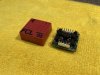
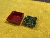
Here is one of the FCL 05 modules removed from the phono stage. As you can see, it is not potted. The cover is simply snapped onto the PCB and glued into place

f1.jpg f2.jpg

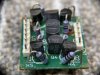
Here is the same module opened, revealing the internal PCB which houses a good few TO-92 transistors, as well as a couple resistors and diodes.

f5.jpg f6.jpg f3.jpg

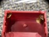
And here is the main culprit of the notorious issues that people have with the FCL modules. The glue which was used to hold the ceramic-plastic covers onto the PCB.
In my case, the FCL modules worked perfectly fine as there was a conservative amount of glue used which meant none of it ended up creeping onto any nearby components.

f4.jpg

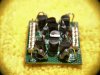
Here is one of the FCL modules completely rebuilt with new TO-92 transistors, as well as a complete reflow and deflux of the PCB. Reattaching the cover to the PCB was as easy as snapping it back into place and adding a small dab of super glue to each corner of the PCB.

f9.jpg f7.jpg f11.jpg
 
Rear section cont'd:

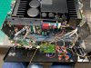
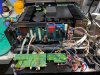
After struggling for a while to get all of the wires resoldered back onto the PCB's, getting the PCB's mounted back into the enclosure, and triple checking my work before buttoning the rear panel back up, it finally looks like an amplifier again. Kyocera really did not have servicing in mind when executing the final product. There is simply not enough slack in the wiring to work with. Many brackets had to be slightly bent to accommodate the removal and reinstallation process of the rear section. It's a shame, but I'm glad it's over with...


h1.jpg h2.jpg


What I will say though is I am very happy that Kyocera did employ the use of modular connectors for most of the wiring. It made the majority of the work go relatively smoothly. The bodged and glued wires to the back of the circuit boards really pisses me off though. You'd think they would have come up with a more elegant solution than they did, but you would be wrong…
 
Last edited:
Final assembly and testing:

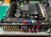
After finalizing the assembly process, I had a working amplifier once again. This was an extremely exhaustive process that took way more time than it should of.
Balancing school and work while trying to work on audio equipment has been extremely difficult for me, which is why this restoration has taken as long as it has.
I also have other customer's audio gear with me waiting for service, so justifying the allocation of time to work on my own equipment is challenging.

q1.jpg q2.jpg q3.jpg q4.jpg
a3.jpg a2.jpg a1.jpg

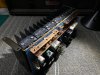
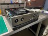
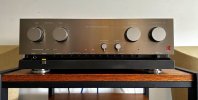
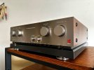
The finished product sitting on my bench after testing and adjustment. isn't she pretty?!

q5.jpg
 
Last edited:
I've had the 910 running for a couple of months now, and what I can say is that for an integrated amplifier, it is extremely impressive. It is perhaps one of the most dynamic and authoritative integrated amplifiers I have gotten my hands on. It takes complete control of my speakers.

After the restoration, I brought it to the previous FrankenFest, and it seemed to get a ton of positive reception when paired with my Phase Technology PC 1.5's.

kyocera4.jpg

I'm very happy to have found this gem, and I am even happier to have been able to restore it and showcase the process here. These amplifiers are incredibly rare, and having a properly documented restoration has the ability to save someone a lot of headaches when repairing or restoring theirs. Thanks everyone for reading along! It was fun! :)
 
I'm not sure if you do repairs like this for others. If I was to bring you a non-working A-910 and paid you to do the same to my unit that you did to yours, how much would you charge? Thanks
 
It doesn’t feel like it, but it’s been over a year since I started the restoration on the A-910. Ever since I finished, there has been a fault which has prevented me from using the phono stage. It turns out that I had installed four capacitors on the back of the board in the wrong location, causing oscillation and DC issues.

BFF418A6-3271-4899-86B3-424D6D816C86.jpeg

Up until recently, I haven’t had any time to fault trace the issue, but this weekend I had a day to dig into it. I’m glad I found the problem, and now the amplifier is up and running 100%.

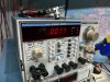
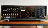
I also took part of the day to properly calibrate the front peak indication LED’s, replace the last original capacitor in the auxiliary power supply, and install an IEC inlet onto the back of the amplifier. I also decided to take some measurements, and found when driven into 8 ohms, I achieved a THD of .007%! A great number, considering this amp was rated for .02% :)
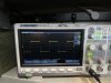
Also, take a look at that square wave performance!

3313C6FF-EB64-4BEE-A4A1-C6B459EC1776.jpeg06548A3A-205B-40D2-A430-B8AFF0FC9D81.jpeg 35385046-27A7-4FD9-BD6C-4D2EB38C5A3F.jpeg


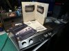
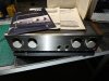
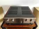
After getting the amplifier back together, I gave it a thorough cleaning after it had been sitting on the shelf all this time. It really looks great! I also have the box and all of the paperwork for it, including factory brochures!

73E7BAA6-B150-4AED-A584-17F4C95335CB.jpeg 05BCCC20-ACC0-445E-AB0F-07A1993BB6A7.jpeg 221DCA3A-3412-4990-9F56-F3F6969A98D4.jpeg 9E69B589-AD98-466F-8504-6C4916B32244.jpeg 2E7CA156-EC10-4A0A-B75B-628B13CAC8BA.jpeg 73173DE6-D232-452E-9A42-FF31B7362CAF.jpeg

I’m on the fence about selling it… I’ve wanted one for years, and now that I finally have one in this good of condition, it’s going to be hard for me to let it go. We’ll see :D
 
Last edited:
I finally recorded and uploaded a video of the A-910 in action to YouTube! It can be found here:

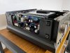
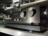
I also took some more pictures, so I will attach them to this post. Hope you enjoy!

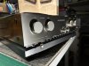
910-1.jpg 910-2.jpg 910-3.jpg 910-4.jpg 910-5.jpg 910-6.jpg 910-7.jpg
 
Nice restore, I commented on your video, I recently did a full restore on a 910, it too is mint. Blown outputs, I have a thread here and DIYaudio on the process of swapping over to TO3P devices (NJW1302/NJW3281). Definitely wasn’t a fun one to work on.

Dan
 
Nice restore, I commented on your video, I recently did a full restore on a 910, it too is mint. Blown outputs, I have a thread here and DIYaudio on the process of swapping over to TO3P devices (NJW1302/NJW3281). Definitely wasn’t a fun one to work on.

Dan
Thanks Dan!
Sorry for not replying to your YT comments, I have been overwhelmed with comments and emails that I am still sorting through. It's extremely time consuming.
Yeah, the 910 front and rear sections are fair nightmares. Lots of patience and finesse is needed to get many of those boards out. Thanks for your support! I'll check your thread out :)
 
Thanks Dan!
Sorry for not replying to your YT comments, I have been overwhelmed with comments and emails that I am still sorting through. It's extremely time consuming.
Yeah, the 910 front and rear sections are fair nightmares. Lots of patience and finesse is needed to get many of those boards out. Thanks for your support! I'll check your thread out :)

Oh no worries at all, I wasn’t saying it for that reason. I am certainly a subscriber to your YouTube channel, working my way through your videos. I just found it funny that we are working on many of the same things around the same time. I did the L-07C, L-07C II, L-07Ms and L-07MIIs right around the same time and I just repaired a pair Sequerra Metronome 7s which I also saw in a video. Cools stuff. I’ve been long thinking about posting videos, but find it hard to find the time, especially now that I have twin toddlers, I applaud you. Maybe someday.

Dan
 
Back
Top Bottom