

You are using an out of date browser. It may not display this or other websites correctly.
You should upgrade or use an alternative browser.
You should upgrade or use an alternative browser.
L Cochrane push pull 6l6 amplifier debug.
- Thread starter trainbuftony
- Start date


trainbuftony
Electron Herder
It's there.
220k resistor to ground
220k resistor to ground

I have noticed some newer designs seem to have an excess of parts for no clear reason. I won't pretend to be a designer but I look at things with a bit of a mechanic's eye. Parts that aren't there can't break. I may have gotten along with Mad Man Muntz in that respect.Both amps (in the pictures) seem to have 4 times as many parts as would be needed. Maybe that's the art of all this--jamming as much and as many goodies as possible under the hood?
floating paraphase. It works and not awfully but its not amazing. Looks like there is one too many stages in the feedback loop though. A typical floating paraphase would have the feedback coming in to the cathode of what you have drawn as the lower tube. The third triode should be outside the loop.I drew out a quick schematic as wired. It looks like one of those self inverting output stages.

He's on record as always using a floating paraphase inverter and minimal feedback.
One of my first DIY projects was a PP 6B4G amp that used a floating paraphase inverter. It was from a schematic by another DIYer, a fairly competent one, and it actually sounded very nice, but definitely not a "stiff" amplifier. ;-)
One of my first DIY projects was a PP 6B4G amp that used a floating paraphase inverter. It was from a schematic by another DIYer, a fairly competent one, and it actually sounded very nice, but definitely not a "stiff" amplifier. ;-)
But a floating paraphase typically uses a voltage divider with 10 times the values shown here, like 560K and 470K. You might check and see if that's the case here. The schematic for the "other" amp in question shows 560K and 470K.

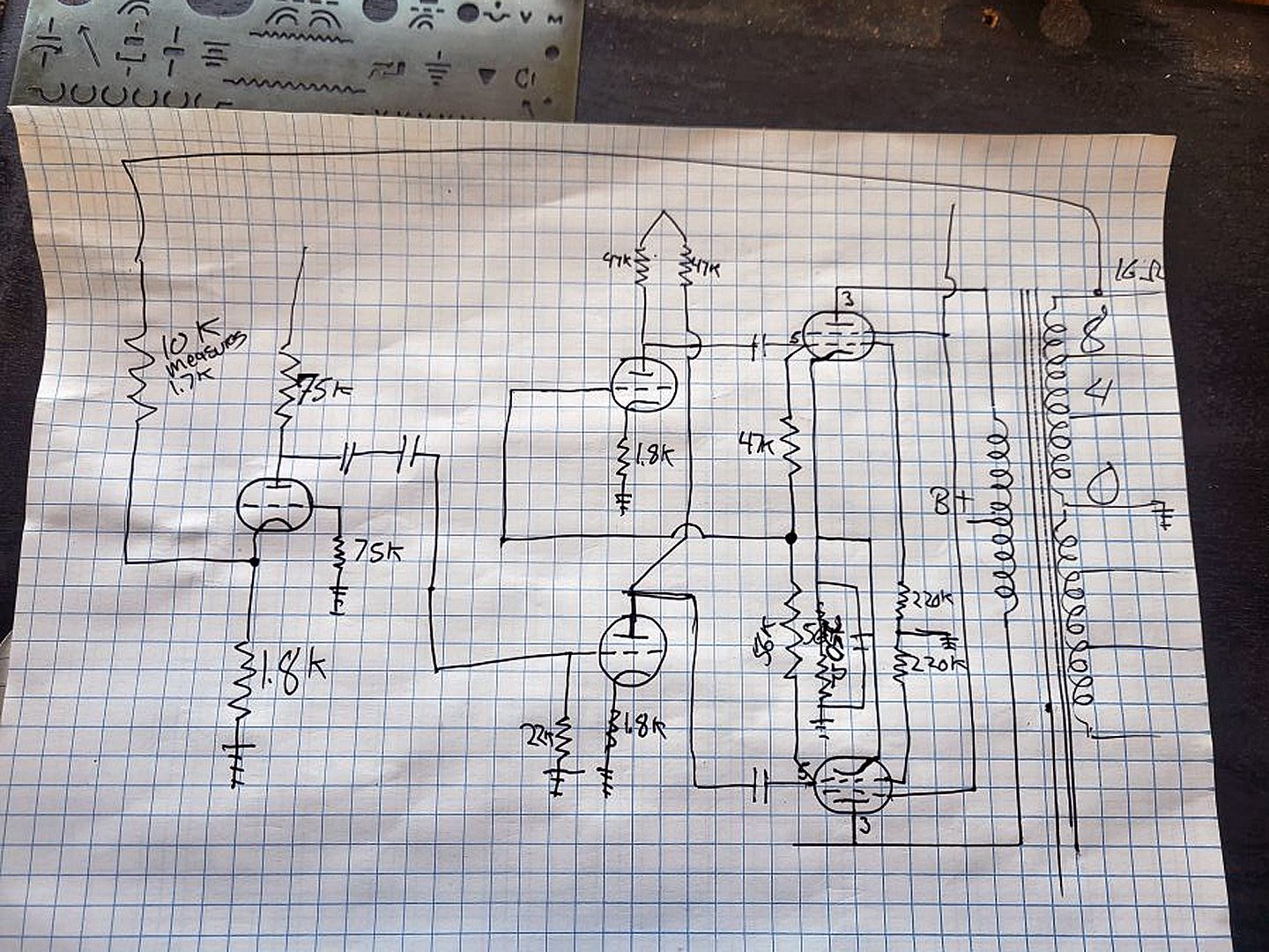
I took the liberty of rotating and enlarging the image. Posting it on Photobucket gives a slightly better resolution than posting directly to this site.
Are there two caps in the series between the input stage and the PI? That is very odd.
trainbuftony
Electron Herder
I took the liberty of rotating and enlarging the image. Posting it on Photobucket gives a slightly better resolution than posting to this site.
Are there two caps in series, between the input stage and the PI? Very odd.
Thanks for the edit.
There are in fact two caps in parallel between the first and second stage. It's that way on both channels.
In fairness to the designer, I'm going to assume that the 56K and 47K voltage-divider resistors, and the 22K resistor from grid to ground on the lower inverter tube are off by a factor of 10, otherwise there would be some serious loading issues that would cause quite a bit of distortion. Otherwise, I can't see why this wouldn't work. Is there a dropping resistor before the output tube screens?
I remember reading that the 56K and 47K resistors are 10% different to balance the two output halves of the phase inverter.I n fairness to the designer, I'm going to assume that the 56K and 47K voltage-divider resistors, and the 22K resistor from grid to ground on the lower inverter tube are off by a factor of 10, otherwise there would be some serious loading issues that would cause quite a bit of distortion. Otherwise, I can't see why this wouldn't work. Is there a dropping resistor before the output tube screens?
trainbuftony
Electron Herder
One is .1uf 630v the other a .22 if I'm reading the markings correctly. They have overspray on them...What are their values?
Thanks!
The resistors are 46k and 56 k respectively. That's how it showed up.In fairness to the designer, I'm going to assume that the 56K and 47K voltage-divider resistors, and the 22K resistor from grid to ground on the lower inverter tube are off by a factor of 10, otherwise there would be some serious loading issues that would cause quite a bit of distortion. Otherwise, I can't see why this wouldn't work. Is there a dropping resistor before the output tube screens?
There are no screen stoppers, no. Dc straight to the screens with no protection.
I'm no expert but I think I remember someone named Dave warning about screen stoppers ESPECIALLY when using excessive power supply reservoir caps.
Am I remembering that right...
Anyway it seems like most competent pentode designs use some form of stopper. This has all 4 screens tied together and a 10k dropping resistor from node that feeds the opt ct.
There's parallel 120uf caps on the screen circuit.
Drawing out the power supply should be interesting.
yeah with very large caps you can produce a situation where the screens can arc badly. The resistors de-tune that setup so its much less prone to happening.
now if they are just fed right from that common 10k with no cap, I doubt it would be a problem but if the screens come from a cap it would be good practice to have 100 ohms or so between the supply and each screen.
curious about the regulation on that screen supply too. Big droppers with screen supplies tend to produce very poor regulation and that does nothing good for performance in a pentode. Probably not a big deal if its only making tiny power before it distorts horribly but if you get that singing at the 20-odd watts it ought to be capable of I'd expect it to drop like a rock.

Mike Stehr
Poverty Audio
Here, I changed it for ya...LOLPretty sure I have a cardboard box that I've been throwing up in that looks similar.

I'm no expert but I think I remember someone named Dave warning about screen stoppers ESPECIALLY when using excessive power supply reservoir caps.
Am I remembering that right...
With tubes of more sane (but yet still considered high) Gm levels however (including 6550, 7591, and EL34), the more typical concern is parasitic activity (and the resulting protection) regarding the screen grid, which is most important when the screen grid operates at a DC voltage level that is very nearly that of the plate voltage. In virtually all such designs, screen stoppers are a must to prevent not only garden variety parasitic issues, but also the very destructive kind that can result in tube destroying output tube arcing.
More screen stopper quotes from Dave:
The only Mac amplifier I'm aware of where they later ultimately removed the plate chokes of the original design is the MC225. When they did so, they then installed previously absent screen stopper resistors -- done no doubt to provide for the general HF stability that the chokes originally provided for, but also to specifically add stability and protection to the screen elements of the 7591 tubes. Without the screen stoppers, the original design was potentially prone to output tube arcing, and the possibly catastrophic collateral damage of taking out an OPT along with it. With the revision, the screen circuit is stabilized to prevent such tendencies, general HF stability is still maintained, with the tubes and output transformers are much better protected. My own 225 came as an early version with the chokes and no stopper resistors (on either the g1 or g2 elements!). During restoration, I also converted the output stage to the later version, using 0.25 watt resistors in both of the stopper positions.

DesertRatt
All Bark, No Bite!
I didn't see any mention of what tube types the small tubes are?
trainbuftony
Electron Herder
Voltage amplifier is a 5814 and the splitter is a 6cg7

maxhifi
Addicted Member
The amp I posted a photo of uses two different types of output tube in push pull parallel, and has way too much gain. It does actually sound decent though* The builder even wound his own transformers! Its construction does kind of remind me of those weird people who have yards full of scrap metal sculptures.Looks to me like s new art form is being created--Electro-Naivety. I've been seeing DIY Tube amps since 1970s and never seen anything like the assemblages shown in this thread.
*up until i heard some random popping sounds and decided not to tempt fate by operating it any longer.
Its an old one but a good oneYa, that picture reminds me of this schematic drawing.
As for the Cocharne schematic, I'm curious to see where this project goes. I'm sure it can be sorted out into a euphonic distortion generator that sounds passable. Or totally reworked into a decent sounding amp with a different circuit, more gain and more negative feedback.
Last edited: