• The move to the new server is done. There are some software and database maintenance updates in process. This has us passing the hat around to help out. We appreciate any donations. Seriously, even a dollar helps. The payment page may be found here - https://www.audiokarma.org/support.html

Late 1960s Fender Deluxe Reverb Issues

captainclock

Pacifist Otaku
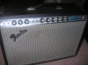
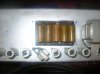
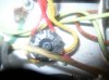
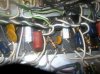
Hello Everyone, the other day I was asked to see if I could get a late 1960s vintage Fender Deluxe Reverb up and running for a friend of mine who's son had gotten it from his school who was about to throw it out because it wasn't working. Anyways it doesn't want to put out any audio when its turned on and the standby switch is switched on (which is supposed to turn on the B+ to the amp from what I read online about it.) I had already tested the B+ on the 6V6s and they tested mostly within specs and the 12AT7s tested mostly within specs and so did the 12AX7, the 7025s however tested at only -0.625 Volts which I'm guessing is where the fault lies.

Anyone on here ever work on this particular amp before and specifically work on an amp with this particular problem before?
Any help would be welcome.

Thanks,

Levi
 

Attachments

  • DSCN2629.JPG
    DSCN2629.JPG
    82.8 KB · Views: 78
  • DSCN2631.JPG
    DSCN2631.JPG
    119.3 KB · Views: 75
  • DSCN2632.JPG
    DSCN2632.JPG
    81.5 KB · Views: 70
  • DSCN2633.JPG
    DSCN2633.JPG
    63.7 KB · Views: 74
Register to hide this ad
Don't know about that amp but those power caps look a little old. Is it solid state or tube rectification?
 
I've had a couple of those in the past - and always regret having sold them...

I'd check for bad solder joints around the 7025 bases and any other regulation caps for the 7025. Have you confirmed all the PS outputs are correct?
Also, does it do that on both channels?
 
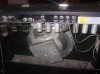
I agree with KB007, skimming schematics for Deluxe Reverbs, it limits what can be bad if all the other tubes test close enough to spec. -0.625v (dc, I would assume) sounds like an open circuit somewhere. The high-voltage caps are most likely good, or blown open, though if so, the 7025s would still have voltage. It is tube rectified, you can see what looks like (and confirmed by the schematic) a 5U4-type rectifier tube.
 
I've had a couple of those in the past - and always regret having sold them...

I'd check for bad solder joints around the 7025 bases and any other regulation caps for the 7025. Have you confirmed all the PS outputs are correct?
Also, does it do that on both channels?

Supposedly the Vibrato/Special effects channel is all good except for the 7025 in that circuit, the Normal Input channel the 12AT7 measures fine but the two 7025s in it are both measuring way below spec. what's interesting is that the two 12AT7s get their B+ from the two output transformers ontop of the chassis (below if you look at it from the perspective of it being installed in the cabinet.)

The -35V power supply rail works as it should and is measuring at about -36 to -38 volts that's going to the Grid of the 6V6s if I remember right.
 
Last edited:
I agree with KB007, skimming schematics for Deluxe Reverbs, it limits what can be bad if all the other tubes test close enough to spec. -0.625v (dc, I would assume) sounds like an open circuit somewhere. The high-voltage caps are most likely good, or blown open, though if so, the 7025s would still have voltage. It is tube rectified, you can see what looks like (and confirmed by the schematic) a 5U4-type rectifier tube.

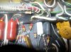
Yes the voltages are measured in DC and I'm guessing that maybe one of the electrolytics on the main circuit board (the 25MFD 35VDC caps) might be why its having issues with extremely low and negative B+ on the 7025s.
 
that is a nice score for your friend's son.....looks to be a 1973 model.

My friend's son scored it himself because his school he went to was throwing it out because it didn't work so he asked them if he could have it and they said that he could, I'm just repairing it for him.
 
I worked on one for a friend a few years ago. It hummed quite badly so I replaced all the power supply caps. Still had quite a bit of hum, so I reworked the grounding scheme to a star ground. That cut the hum voltage by 75% at the speaker terminals. The grounding is all over the chassis and could never be very quiet. The star grounding made it much quieter and sweetened the tone even more.

Good luck,
John
 
I worked on one for a friend a few years ago. It hummed quite badly so I replaced all the power supply caps. Still had quite a bit of hum, so I reworked the grounding scheme to a star ground. That cut the hum voltage by 75% at the speaker terminals. The grounding is all over the chassis and could never be very quiet. The star grounding made it much quieter and sweetened the tone even more.

Good luck,
John
Thanks for the tips, Although I have no idea what this amp sounds like currently since it isn't even putting out any audio right now... :idea: :eek: :( But I tested the power supply caps and the electrolytics that are in the main circuit (all of which are original Mallory Caps) and most of them tested fine using the ohm meter charge up test, but there were two of them on the main board that had flunked the ohm meter charge up test and I'm suspecting that those caps might be what's causing the amp's no audio issue... :idea:
 

Thanks, I'll take a look, maybe his guide will have some tips for repairing/tracking down my no audio issue. :idea:

EDIT: I was looking again at the amplifier and the layout diagram and it looks like this amp may have been modded at one point in time, because this amp only has 5 electrolytics instead of 7 like there's supposed to be on the main board and they are different ratings than what the diagram/scematic calls for, the schematic/layout diagram calls for 7 25 Microfarad 25 Volt Electrolytic capacitors in the main circuit board, but instead there are 4 25 MFD 35 Volt electrolytics and 1 5 MFD 50 Volt electrolytic on the main board which may be part of the reason why this amp is not working right... o_O :idea:
 
Last edited:
Not sarcastic, just funny! It's a great amp that anyone would love to own including me but I'll hang onto my Fender 5E9 for now. ;)

Just out of curiosity, have you checked the main power resistor from the 5U4 tube yet? I had a friend bring me one which had no sound (no B+) and the power resistor was open.

If you are getting good B+ on the 6V6's, maybe take a look at the output transformer.
 
Not sarcastic, just funny! It's a great amp that anyone would love to own including me but I'll hang onto my Fender 5E9 for now. ;)

Just out of curiosity, have you checked the main power resistor from the 5U4 tube yet? I had a friend bring me one which had no sound (no B+) and the power resistor was open.

If you are getting good B+ on the 6V6's, maybe take a look at the output transformer.

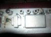
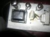
OK Well I wasn't sure, I'm not good at telling the difference between sarcasm or jokes (it comes with the Autism territory), anyways yes I get good B+ on the 6V6s but only when the Standby switch is flipped on (which from what I read online elsewhere supposedly the standby switch is used to switch on the B+ to the tubes and for keeping the tubes warmed up for in between gigs.) anyways the only tubes that don't meaure proper B+ voltages on the plates are the 7025s and thats it, the 12AT7s and the 12AX7 all measure like they're supposed to just not the 7025s. Where's the output transformer on this things exactly? There's three things attached to the top (bottom) of the amplifier chassis that look like they could be output transformers, and which one's the power resistor for the rectifier tube?

EDIT: Just looked at the 5U4GB tube and there doesn't seem to be any resistors attached to it...:idea:
Also what part of the output transformer should I be checking?
 
Last edited:
The standby switch just cuts off the B+ coming from the 5U4 tube. I think those standby switches do more bad than good especially when slamming the tubes with B+ when the tubes have already been warmed up.

Some pics maybe and we can probably show you which transformers are which. I also forgot to mention that my Fender had a non working vibrato which turned out to be one of the 12AX7 tubes was half lit. The heater in 1/2 of it was burned out. In a dark room, look at the 12AT7 and 12AX7 tubes to make sure both halves are lit.

Is there any sound, hum or crackle when your ear is right up to the speaker?

The power resistors are usually square brick looking things attached from one of the pins of the 5U4 tube but can also be color coded high watt resistors.
 
The standby switch just cuts off the B+ coming from the 5U4 tube. I think those standby switches do more bad than good especially when slamming the tubes with B+ when the tubes have already been warmed up.

Some pics maybe and we can probably show you which transformers are which. I also forgot to mention that my Fender had a non working vibrato which turned out to be one of the 12AX7 tubes was half lit. The heater in 1/2 of it was burned out. In a dark room, look at the 12AT7 and 12AX7 tubes to make sure both halves are lit.

Is there any sound, hum or crackle when your ear is right up to the speaker?

The power resistor would be the square brick looking thing attached from one of the pins of the 5U4 tube.

The only sound it makes is the "thump" noise when the Standby switch is flipped, and I noticed that when the standby switch is flipped the 6V6s get a bluish glow to them, but when the Standby switch is turned off the bluish glow goes away on the 6V6s. And no there is no Power resistors attached to the 5U4GB socket anywhere, there is no rectangular ceramic power resistors anywhere in this amp to be found, just a bunch of 1 watt or less carbon comp resistors and that's it.
I tested all of the 12AT7s,the 12AX7, and the 7025s and none of them had any dead filiments, and all tested at well over 100 on the tube tester of mine.DSCN2635.JPG DSCN2636.JPG DSCN2637.JPG DSCN2638.JPG DSCN2639.JPG
 
Thanks, I'll take a look, maybe his guide will have some tips for repairing/tracking down my no audio issue. :idea:

EDIT: I was looking again at the amplifier and the layout diagram and it looks like this amp may have been modded at one point in time, because this amp only has 5 electrolytics instead of 7 like there's supposed to be on the main board and they are different ratings than what the diagram/scematic calls for, the schematic/layout diagram calls for 7 25 Microfarad 25 Volt Electrolytic capacitors in the main circuit board, but instead there are 4 25 MFD 35 Volt electrolytics and 1 5 MFD 50 Volt electrolytic on the main board which may be part of the reason why this amp is not working right... o_O :idea:

This doesn't look modded to me and this iteration may have had a slightly different cap setup. Wasn't uncommon.

Cademan maybe onto something regarding a bad tube or fried resistor. Could even be a bad coupling cap.
 
Back
Top Bottom