

You are using an out of date browser. It may not display this or other websites correctly.
You should upgrade or use an alternative browser.
You should upgrade or use an alternative browser.
Late 1960s Fender Deluxe Reverb Issues
- Thread starter captainclock
- Start date


captainclock
Pacifist Otaku
Capt, I would recommend you join the Hoffman forum -- http://el34world.com/Forum/index.php -- and start a thread there similar to this one. It's a guitar amp-specific site and the guys that hang out there are very experienced amp techs and builders who know Fender amps backwards and forwards. They will not only be able to help with diagnosing the no sound issue , but also advise you on the repairs/mods that have been done and whether they need to be revised, and what else should be done to keep this very nice amp working for your friend's son (who really lucked out on this deal!) . (BTW, this referral to another forum should not be construed as any kind of a knock on AK).
I'll give that forum a try as well.

Joined up with that forum just waiting admin approval right now...
Last edited:
captainclock
Pacifist Otaku
Dang. The kid really scored. Point to point wired Twin Reverb is the end of the line for a lot of musicians. Jerry Garcia used these in the legendary '72 run. Keep at it. This is really worth fixing. Robert
Yeah, that's what I said, it even had a Telefunken tube in one of the tube sockets...


captainclock
Pacifist Otaku
Check the items circled in red. Sorry as I thought the 12AX7 was the AF amp/phase inverter but it is actually (according to the schematic) the 12AT7 tube so try inputting a signal at pin #2 of the 12AT7 tube (circled in yellow)View attachment 661148 .
I'll take a look at those things you circled.

Edit: So I checked out the amp using the sound injection method you suggested only this time using the 12AT7 tube and this time I got audio (albeit very soft audio because I was using the headphone jack on my electronic piano) but I got audio so it means that the power amp stage is fine, and that the problem lies in the preamp stage somewhere like we thought, and I'm suspecting that the horrid mod/repair jobs that were performed on this thing who knows when might have something to do with it (considering that there are a few electrolytic caps missing from the circuit and some other funky mods.)
Last edited:


Assuming you know that new looking choke on top is in a spot that should normally be empty, then it is not a replacement for TR2 on the schematic? Where is TR2 supposed to be located, underneath?
The schematic is kinda weird on the power supply but it clearly has multiple stages of caps/choke/resistors/caps to clean up the B+. Maybe that choke was added by someone who didn't understand that electrolytics go bad and cause hum and should be replaced. Shoot, my dad did the same thing to a Scott receiver when it developed some hum. He was not a technician but knew enough to know that the hum was from the AC line so he added caps to the PS instead of replacing the originals. A choke would perform a similar function.
The schematic is kinda weird on the power supply but it clearly has multiple stages of caps/choke/resistors/caps to clean up the B+. Maybe that choke was added by someone who didn't understand that electrolytics go bad and cause hum and should be replaced. Shoot, my dad did the same thing to a Scott receiver when it developed some hum. He was not a technician but knew enough to know that the hum was from the AC line so he added caps to the PS instead of replacing the originals. A choke would perform a similar function.
as someone else mentioned, it would be a very good idea to replace the electroytic caps in the power supply before running the amp too much longer. circuit design in Fender amps ran components very close to the maximum tolerances. check out the chassis layout and schematic from the fender amp field guide site. http://www.thevintagesound.com/ffg/schem/deluxe_reverb_ab763_schem.gif, and http://www.thevintagesound.com/ffg/schem/deluxe_reverb_ab763_layout.gif
the correct rectifier is a 5AR4/GZ34, not a 5U4. The 5U4 does not have a cathode and probably cannot supply adequate current for the power supply.
the correct rectifier is a 5AR4/GZ34, not a 5U4. The 5U4 does not have a cathode and probably cannot supply adequate current for the power supply.
captainclock
Pacifist Otaku
Assuming you know that new looking choke on top is in a spot that should normally be empty, then it is not a replacement for TR2 on the schematic? Where is TR2 supposed to be located, underneath?
The schematic is kinda weird on the power supply but it clearly has multiple stages of caps/choke/resistors/caps to clean up the B+. Maybe that choke was added by someone who didn't understand that electrolytics go bad and cause hum and should be replaced. Shoot, my dad did the same thing to a Scott receiver when it developed some hum. He was not a technician but knew enough to know that the hum was from the AC line so he added caps to the PS instead of replacing the originals. A choke would perform a similar function.
That would make sense but in pictures of the same amp I saw elsewhere online I saw that there was some sort of transformer or choke in the same spot as the replacement/modern transformer is now.
and the original was tied into the circuit at about the same spot as the new one is. But whether or not its the same value as the original is a whole other story.
Last edited:
captainclock
Pacifist Otaku
That's what I thought maybe it should be using a 5AR4 Rectifier tube, but the original tube placement chart inside the cabinet shows a 5U4GB in the rectifier spot on this amp...as someone else mentioned, it would be a very good idea to replace the electroytic caps in the power supply before running the amp too much longer. circuit design in Fender amps ran components very close to the maximum tolerances. check out the chassis layout and schematic from the fender amp field guide site. http://www.thevintagesound.com/ffg/schem/deluxe_reverb_ab763_schem.gif, and http://www.thevintagesound.com/ffg/schem/deluxe_reverb_ab763_layout.gif
the correct rectifier is a 5AR4/GZ34, not a 5U4. The 5U4 does not have a cathode and probably cannot supply adequate current for the power supply.
I was thinking of trying to get the capacitor kit from over at AES for this amplifier (its only $25+ Shipping) and then replace all of the electrolytic caps in this amp including the ones that are missing according to the layout chart.I don;t believe any Fender Deluxe or Deluxe Reverb ever used a 5U4 as rectifier. The earlier Deluxe models did use a 5Y3 (also non-cathode rectifier), but all reverb models used the 5AR43/GZ34 rectifier tube. I suggest checking the schematics carefully to see what else may have been changed. Good Luck !
captainclock
Pacifist Otaku
I don;t believe any Fender Deluxe or Deluxe Reverb ever used a 5U4 as rectifier. The earlier Deluxe models did use a 5Y3 (also non-cathode rectifier), but all reverb models used the 5AR43/GZ34 rectifier tube. I suggest checking the schematics carefully to see what else may have been changed. Good Luck !
I don't know the tube placement chart inside the cabinet does say "Fender Musical Instruments" on it and then lists the patent notice underneath that.
As you can see in the picture below this is definitely the original tube placement chart and it does list a 5U4GB Rectifier tube in the tube lineup on this amp.
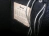
Last edited:
captainclock
Pacifist Otaku
From what I can see on the physical unit vs. the layout chart, the wires on the replacement transformer are attached to the same spot as the original transformer was but whether or not they got the right sized transformer is another thing...That non-original looking transformer is for the reverb circuit. You should be able to trace out and follow the leads to verify with the schematic. Exact replacements are available and really work the best, IMO.
captainclock
Pacifist Otaku
I suggest posting this topic on the Fender Amp forum - fenderforum.com, I believe. Lots of experts on amp repair there.
OK Thanks, I'll check that one out as well.

drew_t
Well-Known Member
The reverb transformer is actually between the third and fourth preamp tubes. It can be seen in the first photo in this thread.That non-original looking transformer is for the reverb circuit. You should be able to trace out and follow the leads to verify with the schematic. Exact replacements are available and really work the best, IMO.
captainclock
Pacifist Otaku
Well Good News Everyone! I got the amp up and running, and it turns out it was just a loose resistor in the filter capacitor circuit that was causing my no audio issue. 
Well that's good news. Get those caps replaced and it'll be reliable for some time to come. You might want to check resistor values too, they drift.
captainclock
Pacifist Otaku
Well that's good news. Get those caps replaced and it'll be reliable for some time to come. You might want to check resistor values too, they drift.
It didn't hum or anything so I think the power supply caps are still good in it yet, surprisingly enough, although I think I might ask the owner if they want to have me replace the power supply capacitors or any of the other electrolytic capacitors in the amplifier.

Congratulations on getting it back into operation. Changing the electrolytics would be a good idea as a preventative step against future problems. A basic set would be about $25 with a good set of Sprage Atoms (recommended) about $65-$70