

You are using an out of date browser. It may not display this or other websites correctly.
You should upgrade or use an alternative browser.
You should upgrade or use an alternative browser.
Latest Thorens to the stable -TD125
- Thread starter ehoove
- Start date
Linn service rack
I've got one of the steel racks that Linn sold to dealers that allowed you to bolt a LP-12 into and lay the table on it's side while you're workin on it. Have simply layed a couple of nice dimensional pieces of lumber across it and it at least does allow getting at the bottom of the TD-125 for things like suspension adjustment -which is a B&*(^h - but any suspension table that doesn't allow you to adjust the suspension from the top with everything in place is to some degree miserable to work on.It seems to come down to cut n try . Not that much fun unless you leave one arm in place (something most of us seem to have a problem with ?
I've got one of the steel racks that Linn sold to dealers that allowed you to bolt a LP-12 into and lay the table on it's side while you're workin on it. Have simply layed a couple of nice dimensional pieces of lumber across it and it at least does allow getting at the bottom of the TD-125 for things like suspension adjustment -which is a B&*(^h - but any suspension table that doesn't allow you to adjust the suspension from the top with everything in place is to some degree miserable to work on.It seems to come down to cut n try . Not that much fun unless you leave one arm in place (something most of us seem to have a problem with ?

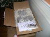
That is packing a table to make sure it gets there in one piece! The smaller box contains the platter, sub platter, arm board and Arm, and accessories. The larger box contains the table and dustcover.
Regards,
Jim
Regards,
Jim
Attachments

Last edited:


Ilikevinyl
Cool Breeze
Jim...Welcome To The Thorens Club!:thmbsp: I love my TD-160 MKI/SME 3009/Denon DL-301 MKII.

JonL
Lunatic Member

tube-a-lou
Addicted Member
Hi all,
I have a Thorens TD 125 MK2 and love it as well, is quiet, staple easy to fix
up, just had to replace the caps on the board a it was set to go. a mod thread
would be great.
Tube
I have a Thorens TD 125 MK2 and love it as well, is quiet, staple easy to fix
up, just had to replace the caps on the board a it was set to go. a mod thread
would be great.
Tube
Ilikevinyl
Cool Breeze
I think I'm a life long member since I have 4 Thorens tables and have owned many since 1972! I bet yours sounds wonderful.
Regards,
Jim
Mine sounds amazing!
Wish I could find a TD-125 cheap!:yes: I bought my mint condition TD-160 MKI for $12! Was in the right place at the right time.

flavio81
Turntable technician
I have had a TD166MK2, TD145MK2 and now a TD125MK2
The TD125MK2 sounds much better than the 145, with the same cartridge and arm!!
On the other hand i put the old TP16 MK I arm (stock arm on Thorens TD125MK2) on the 166 and i thought it sounded pretty nice. I sold it.
My TD125MK2 is now fitted with the TP16 MKII arm (stock arm on Thorens TD145MK2), which is a fairly light (7.5g eff mass) tonearm with removable arm wands.
It sounds detailed, i would say delicate (in a good sense).
The TD125MK2 sounds much better than the 145, with the same cartridge and arm!!
On the other hand i put the old TP16 MK I arm (stock arm on Thorens TD125MK2) on the 166 and i thought it sounded pretty nice. I sold it.
My TD125MK2 is now fitted with the TP16 MKII arm (stock arm on Thorens TD145MK2), which is a fairly light (7.5g eff mass) tonearm with removable arm wands.
It sounds detailed, i would say delicate (in a good sense).

Jim, I am interested in your thoughts on the Magnapan, I am currently building a new plinth for a Denon TT, primarily to address the resonance issues in the Magnapan.
BTW, the TD-150 project is back underway, pics coming soon!
What cartridge are you running in the Unitrac?
Regards,
Jim
I’m not sure which cart is in it now, this is for another local member (c’mon you think I would have a Denon in my rig). My understanding is that this is an inherent problem in the arm itself.
Actually I thought one of the strong suites of the Unitrac 1 was its anti resonance design, as described in the following paper by Magnapan
copied from a VE post:
Part 1:
A Technical paper called: A New Approach in Tracking Arm Design
by Magnepan.
The paper describes the design theory behind Magnepans Unitrac I- arm. At het first page of this paper we read about the mean issue : cartridge mass and compliance factors interact favourably or unfavourably with tracking arm inertia and resonance characteristics. In my Saturnus- story I stated that weight was not the primary issue but resonance frequency. And now we read the word inertia which primary has to do with weight. So could I have been possibly wrong? We will see!
The author adresses this inertia- issue immediately. But he clearly devides the subject into 2 parts.
*Inertia characteristics at subsonic frequencies
*Inertia characteristics at audible frequencies
Inertia can be seen as a kind of slowness, the resistance developed by an object to start moving. Heavy things do not like to get moving, but light things do! That's why we do not like to quarrel with the heavier guys. They tend to resist our physical influence a bit better.
Magnepan likes the arm to be like a feather at subsonic frequencies. But it must be like Saturnus at audible frequencies. Is this possible for the same arm? They hope so. When the arm is extremely light at subsonic frequencies, it will follow all the movements of the stylus tip without loss. This means that there will be no output from the cartridge.
The subsonic region is fed up with all kinds of rubbish and disturbing movements. Indeed we like to banish these bad influence from the amplifier! Not a bad policy! The entire senate would agree with that. Hummm! The arm also would perfectly follow the very slow movement of the groove over the disc, because this groove- movement exhibits a vibrating frequency of nearly zero, but with a relatively gigantic amplitude.
When the arm is super- heavy in the audible frequency- band, really no movement at all at the end of the stylus would be able to move the arm. The only thing to do for the cartridge is: cleverly follow the 2- dimensional trembling of the tip, dictated by the current places of the groove walls. If it did not follow, the stylus would break. In this situation the tip effectively moves the magnet or the coil at the opposite end of the cantilever in relation to the body of the cartridge. And this is exactly what the inventor wanted it to do in the audible frequency range.
Magnepan is one of the few manufacturers who tell us exactly what is the best way of cartridge operation! They precisely point out what the ultimate arm should do for a cartridge. What we must note at this moment is, that Magnepen also means, that the arm itself must develop a distinct division between these two different ways of behaviour. When the arm puts the division too low, we will hear rubbish, and when it is placed too high, there will be a loss of audible information.
At page one they point at a shortcoming of many arms: Where we would need a low inertia (so in this place they mean in the subsonic area) many arms rather high inertia which is primarily due to the design of the counterweight. What they really mean at this moment is, that the arm has high inertia where it should be low. That is in the subsonic region. In this region the rubbish resides, so that we hear the rubbish through the amplifier.
The publishers condemn fluid damping at page 1 too, which would resist the movement in the subsonic region, where there should be no inertia. So they conclude, that damping seems to introduce inertia in the subsonic region. IMO this last objection is not entirely correct.
Now my -of coarse impartial- question must be: Have Magnepan perfectly succeeded in reaching these results when they designed this arm? They wanted to have zero inertia below the mentioned division. This means perfect pliability to the movement of the tip. For this they made the arm of carbon fibre, which reduces pure mass. So at this place they say: below the division we want that the movement of the tip can easily move the arm. Indeed, here me meet the pure mass- issue. But note that we want as LITTLE as possible of it here!
Perfect docility below the division is promoted by low pivot friction too. Magnepan states, that they have achieved that. The influence of the counterweight on the wanted low inertia below the division is defined as follows: the counterweight sits very close to the pivot, so the influence of ist weight , measured near the tip is very low.
For the region above the division the designers wanted a very large inertia.
The rubber suspension of the stylus is situated near the internal end of it, where the electric signal must be generated. So the if false arm movements occur, these will have a nearly unmuted influence on the signal.
But the part of the stylus between the tip and the support is larger than the inner part of the stylus. So the tip movement itself will be muted instead. The conclusion of the author is, that the arm movement is amplified relative to the tip movement. So he really wants the arm to have a very large, non- resonating inertia above the division. To him it was clear now, that he wanted to have a large amount af mass above the pivots to damp the internal arm beam vibrations at and above the division, which could enter the pivot area from the foreside. Just to prevent them from returning towards the cartridge. This mass, they say, will reduce in this way the amplitude of the system resonance which they have used to create the division.
To illustrate why the designers wanted to use the system's resonance I would like you to carry out a small experiment. For this you will need your granny's longest knitting needle. So send Granny to her sister, if she still has one. But stay at home yourself, of coarse! When she has gone, you put a large cork at the sharp end of the needle. Then you take the knob at the other end between two fingers.
The entire process, that you will see now is clearly divided into three regions.
1. Move the knob lowly up and down over a vertical distance of 10 centimeters (those bloody european units). Slowly means a very low frequency, perhaps one Hertz. You will see, that the cork at the end exactly will copy the movement of the knob.
2. When you increase the rhythm of your movement the knob will move faster and faster over the same vertical distance. Suddenly you will note that you will succeed to attain a rhythm, where the cork will start to vibrate in a uncontrollable way. You will discover, that you will only need a much lower amplitude than this 10 cm to keep the thing moving, and also, that the cork will move exactly in the opposite direction to the knob. This means there is a strong amplification and a opposed phase behavior. This situation is what we call resonance. The rhythm in this situation is known as the resonance frequency.
3. When you would increase the movement velocity still further after this moment, you will see, that the movement of the cork will be muted strongly. A steady situation will be established after further increase of the speed , showing up with no movement at all at the cork- side. In this situation you are perfectly able to move the knob at this high velocities within a very large range of amplitudes. This region is clearly situated above resonance, where as the first region was situated below resonance.
Now we only must realize that the knob of Grannies needle is the input signal: the tip movement. The cork is the output signal: the position of the arm tube.
The situation at the resonance frequency. The arm vibrates fiercely. The tip only needs to move slightly to cause this huge arm movements.
The tip and the arm move in mutual anti-phase: exactly in the opposite direction towards each.
Part 2 follows
Regards,
Jim
Copied from a VE Post
Part 2:
Region 1:
The lowest frequencies: the arm's position is an exact copy of the tip movement. The movement flows unmuted through the system. So there is no inertia at all, no resistance or filtering of movement. Because there is no relative movement between arm and tip, the stylus cannot move relative to the cartridge body. So there will be no electric output.
Region 2: other. There is an amplification of the tip's amplitude towards the amplitude of the arm motion.
Indeed there is little restriction to the movement of the tip. But what's more: the arm likes to beat the tip on its talents: it even outperforms it. There is extremely little inertia, very little resistance to movement. The tip moves fiercely relative to the cartridge body, so there will be a large output whereas the tip only needs slight amplitudes. So there is a huge electric output.
Region 3:
The arm is in perfect peace. No movement at all. The tip can move freely, the arm's position is looks like being fixed. There is a extremely large resistance against movement. The motion is filtered- out totally. This is what the designer called: infinite inertia. We must conclude, that the arm is much to slow, there is no docility at all.
Seen from the arm, the tip is fully able to move with all possible amplitudes, freely following the audible range-exitations forced on it by the groove walls. So the audible signals are perfectly transported to the signal- generator placed within the cartridge.
The electric outputs for these regions are:
Input from region 1; no output
Input from region 2; huge output, even slow input signals are amplified
Input from region 3; normal output, no amplification, but all amplitudes are possible.
I can imagine, that you see region 2 as a problem child. Well, it really can be. That is, when the resonance frequency is situated is a frequency region, where we find much rubbish on the disc. We talked about this region before. It is found below 5 Hz. We are glad however, to have found a perfect silent region, from 5 until approximately 15 Hz, where we find the steeply increasing flank of the audible band. When we put the resonance frequency at least at one full octave above the highest disturbances, so at 2 times 5 equals 10Hz. we will have built the perfect disturbance filter.
This is exactly what Magnepan has built- in in the design of the arm and what Mr Ladegaard has proven by means of the results of his experiments. The arm design shows up with a very low effective mass, to reach resonance frequencies, which are situated high enough to establish a suitable seismic filter. The danish paper succeeds in illustrating the audible benefits and forms a clear confirmation of the theology followed by Magnepan. So at last we have reached our mutual amplification!
A long but interesting read!
Regards,
Jim
Part 2:
Region 1:
The lowest frequencies: the arm's position is an exact copy of the tip movement. The movement flows unmuted through the system. So there is no inertia at all, no resistance or filtering of movement. Because there is no relative movement between arm and tip, the stylus cannot move relative to the cartridge body. So there will be no electric output.
Region 2: other. There is an amplification of the tip's amplitude towards the amplitude of the arm motion.
Indeed there is little restriction to the movement of the tip. But what's more: the arm likes to beat the tip on its talents: it even outperforms it. There is extremely little inertia, very little resistance to movement. The tip moves fiercely relative to the cartridge body, so there will be a large output whereas the tip only needs slight amplitudes. So there is a huge electric output.
Region 3:
The arm is in perfect peace. No movement at all. The tip can move freely, the arm's position is looks like being fixed. There is a extremely large resistance against movement. The motion is filtered- out totally. This is what the designer called: infinite inertia. We must conclude, that the arm is much to slow, there is no docility at all.
Seen from the arm, the tip is fully able to move with all possible amplitudes, freely following the audible range-exitations forced on it by the groove walls. So the audible signals are perfectly transported to the signal- generator placed within the cartridge.
The electric outputs for these regions are:
Input from region 1; no output
Input from region 2; huge output, even slow input signals are amplified
Input from region 3; normal output, no amplification, but all amplitudes are possible.
I can imagine, that you see region 2 as a problem child. Well, it really can be. That is, when the resonance frequency is situated is a frequency region, where we find much rubbish on the disc. We talked about this region before. It is found below 5 Hz. We are glad however, to have found a perfect silent region, from 5 until approximately 15 Hz, where we find the steeply increasing flank of the audible band. When we put the resonance frequency at least at one full octave above the highest disturbances, so at 2 times 5 equals 10Hz. we will have built the perfect disturbance filter.
This is exactly what Magnepan has built- in in the design of the arm and what Mr Ladegaard has proven by means of the results of his experiments. The arm design shows up with a very low effective mass, to reach resonance frequencies, which are situated high enough to establish a suitable seismic filter. The danish paper succeeds in illustrating the audible benefits and forms a clear confirmation of the theology followed by Magnepan. So at last we have reached our mutual amplification!
A long but interesting read!
Regards,
Jim