• The move to the new server is done. There are some software and database maintenance updates in process. This has us passing the hat around to help out. We appreciate any donations. Seriously, even a dollar helps. The payment page may be found here - https://www.audiokarma.org/support.html

Leestereo's Marantz 1090 Restoration/Upgrade

Leestereo

Super Member
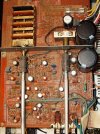
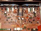
Here are some pictures of the Marantz 1090 as received:

1090 Stock 1 AK.jpg

1090 Stock 2 AK.jpg

The restoration/upgrade plan for this Marantz 1090 consists of the following:
1. Replace all of the power supply electrolytic capacitors with higher spec. 105°C low ESR types
2. Replace all of the signal path capacitors, as appropriate, with either audio grade electrolytic types, film types or C0G/NPO types.
 
Last edited:
Register to hide this ad
Not having a chance to work on one of these yet I'll enjoy following along on what I know will be a quality rebuild. Thanks for sharing! :thmbsp:
 
Not having a chance to work on one of these yet I'll enjoy following along on what I know will be a quality rebuild. Thanks for sharing! :thmbsp:

The Marantz 1090 appears to be a relative rare model; this is only the second one that has crossed my bench over the years.
 
Phono Stage Restoration/Upgrade


Signal Path Capacitors:

The stock capacitors in the input high-pass filter (C401, C402) were 1µF tantalum capacitors and these were replaced with 0.47µF Panasonic stacked polyester film capacitors. The resultant F3 of the high-pass filter with the 0.47µF film is more than adequate at 0.34Hz.

The stock capacitors in the low-pass filter (C407, C408) were ordinary 30pF ceramic capacitors. These were replaced with C0G/NPO capacitors of the same value. The F3 is 5.3MHz (a low-pass should have a F3 of at least 1.5MHz to have minimal phase shift at 20 kHz). The C0G/NPO capacitor type is a Class 1 ceramic capacitor with excellent properties: they are very temperature stable (0 ppm/K); have very low electrical losses with a dissipation factor of ~0.15%; and no degradation in performance with age. They are considered by many to be superior to silver mica types.

The stock C405/C406 capacitors in the Miller feedback loop were also ordinary 30pF ceramic capacitors and as with C407/C408, were replaced with C0G/NPO capacitors of the same value.

In the stock RIAA circuit (3180µs equalization), C415 and C416 were 100pF ceramic capacitors, each of which were paralleled with a 1100pF polyester films (C413 and C414, respectively). Each stock pair was replaced with a single high quality 1200pF polystyrene capacitor.

The stock capacitors in the output high-pass filter were 2.2µF low leakage electrolytics and these were replaced with 1µF Panasonic stacked film capacitors; the F3 of this filter is now 0.59Hz.

The stock C409, C410 capacitors, which determine the low end roll-off of the RIAA equalization, were garden-variety 100µF/10V, 85°C electrolytics. These were replaced with 220µF/16V Rubycon ZLH 105°C, low ESR types. A bi-polar electrolytic replacement would have been my preferred choice, but the limited space precluded this option.


Power Supply Capacitors:

The capacitor (C423) that shunts the zener in the phono stage, was a 47µF/50V electrolytic; the replacement was a 105°C low ESR type (120µF/50V Nichicon PW).

The local DC filtering capacitor, C424, was a 10µF/50V electrolytic and was replaced with a Panasonic FC 100µF/50V.

1090 phono label.jpg
 
Last edited:
Main Power Supply Restoration/Upgrade

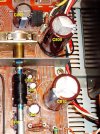
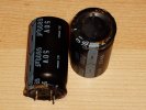
The stock main power supply capacitors, C809, C810, are rated at 6800µF/50V and were replaced with United Chemicon KMQ 105°C low ESR capacitors of the same rating. The initial plan was to increase these capacitors to 8200µF or 10,000µF, but the configuration of the original solder pads limited the possible replacement capacitors. The stock capacitors use an obsolete 3 pin configuration which has a lead spacing of 15mm between the +ve and -ve terminals and the "dummy" terminal is 10mm from either "live" terminal. The replacement capacitor has a standard 10mm lead spacing and was installed with one lead in the "dummy" terminal solder pad which was then bridged to the "live" terminal.

The C802 capacitor is the main filter for the regulated power supply for the phono and preamp stages. The stock capacitor was a 220µF/63V electrolytic and the replacement was a 470µF/63V Nichicon PM low ESR capacitor.

The stock C803 capacitor was a 47µ/25V electrolytic and was replaced with 100µF/25V Nichicon PM low ESR capacitor.

The stock C804 capacitor was a 10µF/35V electrolytic and was replaced with a 22µF/50V United Chemicon KZE low ESR capacitor.

The stock C805 capacitor was a 47µ/25V electrolytic and was replaced with a 100µF/25V Nichicon PM low ESR capacitor.

The stock C806 capacitor was a 47µ/50V (erroneously listed as 470µF/50V on the schematic) electrolytic and was replaced with a 120µF/50V Nichicon PM low ESR capacitor.

1090 power supply label.jpg

1090 main caps.jpg
 
Last edited:
Very interesting project. Are you considering replacing any resistors? Rumor has it that certain other Canadians have had good results with such replacements - specifically sound quality improvements.
 
I hate them old 3 pins. I just did a 2010 (had qty of 2 the 3 pin) and wanted to use the Nichicon KS (10mm snap in) so a gentle slight bend on the legs and a decent fit. I was very happy with the result and not limited to choices on caps.


Main Power Supply Restoration/Upgrade

The stock main power supply capacitors, C809, C810, are rated at 6800µF/50V and were replaced with United Chemicon KMQ 105°C low ESR capacitors of the same rating. The initial plan was to increase these capacitors to 8200µF or 10,000µF, but the configuration of the original solder pads limited the possible replacement capacitors. The stock capacitors use an obsolete 3 pin configuration which has a lead spacing of 15mm between the +ve and -ve terminals and the "dummy" terminal is 10mm from either "live" terminal. The replacement capacitor has a standard 10mm lead spacing and was installed with one lead in the "dummy" terminal solder pad which was then bridged to the "live" terminal.

The C802 capacitor is the main filter for the regulated power supply for the phono and preamp stages. The stock capacitor was a 220µF/63V electrolytic and the replacement was a 470µF/63V Nichicon PM low ESR capacitor.

The stock C803 capacitor was a 47µ/25V electrolytic and was replaced with 100µF/25V Nichicon PM low ESR capacitor.

The stock C804 capacitor was a 10µF/35V electrolytic and was replaced with a 22µF/50V United Chemicon KZE low ESR capacitor.

The stock C805 capacitor was a 47µ/25V electrolytic and was replaced with a 100µF/25V Nichicon PM low ESR capacitor.

The stock C806 capacitor was a 47µ/50V (erroneously listed as 470µF/50V on the schematic) electrolytic and was replaced with a 120µF/50V Nichicon PM low ESR capacitor.
 
Nice work.
BTW. Did you happen to do performance measurements before starting work on the amp for and after comparisons?
 
Very interesting project. Are you considering replacing any resistors? Rumor has it that certain other Canadians have had good results with such replacements - specifically sound quality improvements.
I think I even know whose basement those metal film resistors came from...I may change out the resistors at a later date, but this project was primarily initiated to examine the effects of upgrading the capacitors in filters and feedback loops with film and/or C0G/NPO capacitors.
 
I hate them old 3 pins. I just did a 2010 (had qty of 2 the 3 pin) and wanted to use the Nichicon KS (10mm snap in) so a gentle slight bend on the legs and a decent fit. I was very happy with the result and not limited to choices on caps.

Good idea to use snap-in types for these situations since that kind of termination can be manipulated without risking damage to the capacitor seal.
 
This may be a dumb question, but were the Panasonic stacked film the ECQ series and the polystyrene one the ECW series?
 
Any changes to the diodes in the p/s?

I like to use "soft recovery" types (e.g. UF400x, or UF540x) for replacement of axial diodes in many of my restorations, but the 1090 uses a bridge and a pair of dual diodes and I don't know of soft recovery diodes with the appropriate form factor.
 
This may be a dumb question, but were the Panasonic stacked film the ECQ series and the polystyrene one the ECW series?

Yes, the Panasonic stacked film capacitors I used are the ECQV types; these are polyester types. The Panasonic ECWF type is a polypropylene film. The polystyrene capacitor in the phono stage is a Xicon brand (available from Mouser); polystyrene capacitors are increasingly difficult to find and Mouser is one of the few component suppliers that stock them, Parts Connexion is another.
 
Preamp Stage Restoration/Upgrade


Signal Path Capacitors:

The stock capacitors in the input high-pass filter (CE01, CE02) were 0.47µF low leakage electrolytic capacitors and these were replaced with 0.47µF Panasonic stacked polyester film capacitors. The F3 of this high-pass filter is 0.34Hz. Note that one could use a smaller value(0.22µF or even 0.1µF) higher quality polypropylene capacitor as a replacement, if desired.

The stock phase compensation capacitors, CE03 and CE04, in the local negative feedback loop were ordinary 68pF ceramic capacitors. These were replaced with C0G/NPO capacitors of the same value.

Similarly, the stock capacitors (CE17, CE18) in the Miller feedback loop were also ordinary 100pF ceramic capacitors and were replaced with C0G/NPO capacitors of the same value.

The output capacitors of the first preamp gain stage, CE05 and CE06, were 4.7µF/25V low leakage electrolytics and these were replaced with 4.7µF/50V Nichicon FW Audio Grade electrolytic capacitors.

The stock capacitors in the input high-pass filter (CE07, CE08) of the second preamp stage (following the tone controls) were 0.47µF low leakage electrolytic capacitors and these were replaced with 0.47µF Panasonic stacked polyester film capacitors.

The output capacitors of the 2nd preamp stage, CE11 and CE12, were 4.7µF/25V low leakage electrolytics and these were replaced with 4.7µF/50V Nichicon FW Audio Grade electrolytic capacitors.


Non-signal Path Capacitors:

The local DC filtering capacitor for the preamp stage, CE19, was a 10µF/50V electrolytic and was replaced with a 100µF/50V Sanyo CA 105°C low ESR type.

The filtering capacitors CE15, CE16 were 10µF/50V electrolytics and were replaced with 22µF/50V Panasonic FR low ESR types.

The stock bypass capacitors CE09, CE10 were 100µF/10V electrolytics and these were replaced with 100µF/25V Panasonic FR low ESR types.


1090 preamp label.jpg
 
Last edited:
The "dual diodes" appear to be DS-133 (common cathode). If so, how about something like the On Semi MUR1620? (TO220 package)?
 
Last edited:
So, I'm curious what characteristics caused you to choose the polystyrene over polypropylene? I thought the ECW series was de rigeur? Perhaps it's capacitance availability?
 
Back
Top Bottom