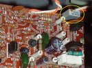
Main Power Amp Restoration/Upgrade
Signal Path Capacitors:
The stock capacitors in the input high-pass filter (C701, C702) were 2.2µF low leakage electrolytic capacitors and these were replaced with 1.0µF Panasonic stacked polyester film capacitors. The F3 of this high-pass filter is 3.1Hz.
The stock capacitors in the low-pass filter (C705, C706) were ordinary 100pF ceramic capacitors. These were replaced with Wima FKP2 polypropylene capacitors of the same value. The F3 of the low-pass filter is 1.6MHz.
The stock C733, C734 capacitors, which determine the low end cut-off of the negative feedback loop, were garden-variety 100µF/16V, 85°C
polar electrolytics. These were replaced with 100µF/16V Nichicon MUSE ES
bi-polar
The stock phase compensation capacitors (C740 and C741) in the negative feedback loop were ordinary 20pF ceramic capacitors. These were replaced with C0G/NPO capacitors of the same value.
Non-signal Path Capacitors
The capacitor (C704) which shunts the input differential stage zener, was a 10µF/35V electrolytic and was replaced with a 33µF/50V Panasonic FM 105°C low ESR type.
The local decoupling capacitors (C735, C736) were 10µF/50V electrolytics and were replaced with 47µF/50V United Chemicon LXZ low ESR types.
The filtering capacitors for the protection circuit (C711 and C712), were 100µF/35V electrolytics and these were replaced with 120µF/50V Nichicon PW low ESR types.
The capacitors C723, C724, C725 and C726 which shunt the output sampling diodes in the protection circuit were 10µF low leakage electrolytics and these were replaced with 10µF/35V Silmic II audio grade capacitors (somewhat overkill here, but these were the only "low leakage" 10µF caps I had on hand).
Other Upgrades
The open frame trimmer resistors (R771 and R772) used for setting the bias current were replaced with 500ohm mutlti-turn types. The idle current was increased to 25mA from 13mA (the heat sink is still very cool to the touch at the higher setting).
The capacitors in the preamp muting circuit, CV03, CV04 and CV05 were replaced with same value capacitors. Note that CV04 was a 330µF/10V capacitor rather than a 220µF/10V as indicated on the schematic; similarly, CV05 was a 47µF/63V capacitor rather than a 47µF/6.3V as indicated on the schematic.