• The move to the new server is done. There are some software and database maintenance updates in process. This has us passing the hat around to help out. We appreciate any donations. Seriously, even a dollar helps. The payment page may be found here - https://www.audiokarma.org/support.html

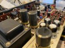
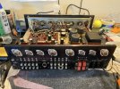
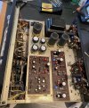
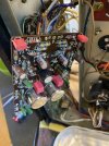
Leestereo's Restoration and Upgrade of a Sansui AU-777A

Which are the smaller output transistors / driver transistors in 777 & 777a Sansui amplifier.
My apologies, I made a big 'assume' about the type numbers. :rolleyes:

Personally, I tend to leave driver transistors alone if they are working, and if they are not a 'badly behaved with age' type.
 
Last edited:
My apologies, I made a big 'assume' about the type numbers. :rolleyes:

Personally, I tend to leave driver transistors alone if they are working, and if they are not a 'badly behaved with age' type.
Still based on your experience can't you suggest the
2sd152
2sd154
2sd143
Replacement Transistors if possible.
In mine the driver Transistors & smaller output transistors are bad & partially working with quite much of distortion
 
My apologies, I made a big 'assume' about the type numbers. :rolleyes:

Personally, I tend to leave driver transistors alone if they are working, and if they are not a 'badly behaved with age' type.
I could not find a recommended substitute for my smaller output transistors NEC 2SD143's on my 777a and opted to just keep the originals since they are testing fine. But it would be good to know a replacement for them if I ever need them?
 
You are right. the MJE 21132 is taken from my data. Probably it is mistake. I replaced 2sd143 with 2SC2073. Work well but you have to be an experienced in electronic world to do such job.
 
Still based on your experience can't you suggest the
2sd152
2sd154
2sd143
Replacement Transistors if possible.
In mine the driver Transistors & smaller output transistors are bad & partially working with quite much of distortion
I would defer to Leestereo for his recommendation, this is his thread for his detailed restore. I have never restored one of these, familiarity with what works for various models is quite an art, so I don't feel it's my place to suggest substitutes in this case.
 
Last edited:
Still based on your experience can't you suggest the
2sd152
2sd154
2sd143
Replacement Transistors if possible.
In mine the driver Transistors & smaller output transistors are bad & partially working with quite much of distortion
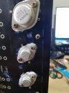
the above 3 are TO-66 , the only TO-66 I know would work > 2N3054
Sadly they are now EOL

I had found some NTE 2N3054 on digikey but are under Export Restrictions

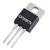
2SC2073 is TO-220-3
1689350787232.png


20210926_154137.jpg
20211015_202739.jpg

install 2N3054 on my 777 too
20210808_171715.jpg
 
FYI , the reason some find the 2N3054 don't work well is because of leg is narrower then those 2sd143/144/152,

NOTE how the leg are too close to edge of mounting hole imprint. may causing A short to the chassis when install improperly ,resulting distortion while playing on the affected channel.
I had done some experiment on this.

20211017_131659.jpg

Solution > worry I might break the leg when apply to much force , I choose to enlarge the mounting hole on the Chassis.

20211004_215701.jpg
20211023_183304.jpg
 
Last edited:
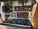
I am finishing up a restoration of my 777a and have a question on how to check/adjust the VR001 trimmer on the F1153 Power/Protector board? I replaced the trimmer and set it to ohms of original I removed, but figured it should be checked and adjusted as part of rebuild. Where do leads of mm connect and what value do I set it to? Nothing in the service manual on it. See pics of my work following this post as a guide.
 

Attachments

  • IMG_4472.jpeg
    IMG_4472.jpeg
    159.2 KB · Views: 43
  • IMG_4473.jpeg
    IMG_4473.jpeg
    130.2 KB · Views: 43
  • IMG_4474.jpeg
    IMG_4474.jpeg
    185.2 KB · Views: 44
  • IMG_4471.jpeg
    IMG_4471.jpeg
    209.7 KB · Views: 44
  • IMG_4481.jpeg
    IMG_4481.jpeg
    178.9 KB · Views: 44
I am finishing up a restoration of my 777a and have a question on how to check/adjust the VR001 trimmer on the F1153 Power/Protector board? I replaced the trimmer and set it to ohms of original I removed, but figured it should be checked and adjusted as part of rebuild. Where do leads of mm connect and what value do I set it to? Nothing in the service manual on it. See pics of my work following this post as a guide.
Checking back in on this question about the Protector Circuit adjustment trimmer on the F1153 Power board and if it needs to be checked/adjusted after a restoration? I cannot find any instructions on how to adjust it anywhere online, but figured it should be done after a full recap? Also, is there any way to test the protector light bulb? I hooked a 9-volt battery and got a faint glow, so I guess it works?
 
I'm not sure if the protection circuit works the same as the one on my 555 but from what I could figure out, if you can turn it up to full power and it doesn't kick in, it's probably adjusted about right. The best I could determine, you'd adjust the pot so the protection kicks in just above full power. I know what you mean about the lack of info on this though and I could be wrong. It had an SCR that grounds the signal and since SCRs are latching, you had to turn the unit off to reset it. The concensus from the guys who know more than me was that the protection circuit is problematic and to just remove the protection circuit on the 555 completely. The fuses are still there on the 555 for protection and it looks like the 777 has them too.
 
I'm not sure if the protection circuit works the same as the one on my 555 but from what I could figure out, if you can turn it up to full power and it doesn't kick in, it's probably adjusted about right. The best I could determine, you'd adjust the pot so the protection kicks in just above full power. I know what you mean about the lack of info on this though and I could be wrong. It had an SCR that grounds the signal and since SCRs are latching, you had to turn the unit off to reset it. The concensus from the guys who know more than me was that the protection circuit is problematic and to just remove the protection circuit on the 555 completely. The fuses are still there on the 555 for protection and it looks like the 777 has them too.
I guess if the protection circuit is not kicking in without reason there is no reason to adjust the trimmer on the power/protection circuit? I just thought maybe it would need to be set to ensure the protection circuit actually kicks in if needed, but if that isn't really necessary either and the whole circuit is sometimes bypassed completely, then I dont need to worry about checking it? I never crank my stereo that loud, and this 777a is plenty loud at just 1/4 turn of the volume knob, it has a very powerful sound for just 30 watts, absolutely amazing amp, my favorite so far! I am completely done restoring it and only had that protection board trimmer not addressed. Unless anyone chimes in with advice to check/adjust it, I will just leave it alone.
 

Attachments

  • IMG_4519.jpeg
    IMG_4519.jpeg
    151.7 KB · Views: 28
  • IMG_4512.jpeg
    IMG_4512.jpeg
    129 KB · Views: 28
  • IMG_4518.jpeg
    IMG_4518.jpeg
    193.6 KB · Views: 28
Here's a link to my 555 thread starting at where the protection circuit is being discussed - https://audiokarma.org/forums/index.php?threads/brians-au-555-restoration.1026772/post-16406557

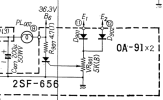
I looked at a 777 schematic and don't see a VR001. I did find VR901 that's the protection circuit adjustment on this schematic at least. Looks similar to the 555 crowbar circuit. Voltage goes to D901/902 and is rectified if it's AC. VR901 adjusts how much voltage gets to the gate of the SCR. When the SCR hits its trigger voltage it grounds the 36.3V supply. So I think adjusting the VR so it doesn't trigger at full volume works. If a transistor shorts, it should be more than really needed to trigger the SCR even if you have the VR adjusted a little high so I don't think the adjustment is super-critical as long as it doesn't trigger in normal operation. If you do accidentally trigger the SCR, you have to turn the amp off for long enough that caps discharge and the SCR unlatches to reset it. I hope if I'm misunderstanding how this works, someone will chime in.

Screenshot 2023-08-15 094850.png
 
Last edited:
The KSC945C were used as replacements for this project since their specs. are a better match to the original 2SC458LG than the KSC1845:
A. KSC945 fT (300MHz) is comparable to that of the 2SC458 (230MHz), whereas the KSC145 fT at 110MHz is quite a bit lower (although that is more than adequate for AF use)
B. KSC945 Ic (150mA) is higher than 2SC458 (100mA), whereas KSC1845 Ic is again lower at 50mA (although not likely to be an issue for signal amplification).
C. KSC945 Noise Figure is 4dB which matches the 2SC458 NF; the KSC1845 is described as a low noise device, but its difficult to compare directly since its spec'd as 25mV (which I think is lower than 4dB)

The lower noise level of the KSC1845s might be advantageous in a phono stage where the gain is very high, but for this 777A project, the decision was to use the closest match to the original 2SC458LG. If the original transistors had been 2SC1312/2SC1313, I probably would have used KSC1845 replacements as was done for the late production 555A in this thread: Repair and Upgrade of a Previously Recapped Sansui AU-555A

how thoroughly lee addresses everything. Love his work!!!
My au777D is in the hands of my AK buddy SHOJAM , who has recapped it to Lee's standards .Hes the first one to taste the fruit !
 
Yesterday shojam said that the amp was louder in one channel than the other by a significant bit.
The sound was like 30% lower in the right channel. Breaking down the issue he found one bad rusty legged 458 transistor in that pre amp pcb.
He showed me the rusty and infact amputated transistor. So he Replaced it with a 669 something.
Later that hour , he told me the amp had a raised tone in the 1000 hz region.
Otherwise the amp was sounding great.
So he found some 1815s in his inventory bag , replaced those 669s with 1815s and was smiling again at the glorious sound of the AU-777D.
He feels that all the small transistors should be revised .
Ofcourse a very even sounding ,natural tone is desirable here.
Comments plz.
 
Back
Top Bottom