• Please note that Audiokarma will be offline briefly for updates early on Monday morning, September 28th.

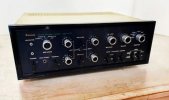
Leestereo's Restoration and Upgrade of a Sansui AU-777A

All board are solder to the chassis and to the ground. I have 0V between the ground and the chassis (tested with each board)

I have replaced a couple of capacitor that are linked to the ground but nothing change. So I decide to check all the voltage that are in the schematics and it's not good.

I tested my output transistors 2SD218 have a low hfe (15, 16, 9,5 and 4,6) with RLC meter. Instead of the 2SD143, on one channel, I have 2 NEC D381 (TO220) that are ok (HFe >50), on the other channel i have on 2SD143 (Hfe 38) and one 2N3054 (Hfe 7).

Do you think that the transistor with low Hfe are dead ?

I measure the power supply and the test point of the board. here are the values :
Output transfo main : 50,6Vac
B0=B1=B2 = 67,3V
B3= 32,0V / B4 = 27,16V / B5 = 12,5V / B6 = 23,5V / B7 = 65,7V / B8 = 65,8V

Point Board F11831 :
1 = 0V / 2 = 23,3V / 3 = 3,8V / 4 = 3,2V / 5 = 62,5V / 6 = 1,18V / 7 = 65,6V / 8 = 0,01V
Point Board F1170 :
1 = 62,7V / 2 = 32,9V / 3 = 32,0V / 4 = 1,18V / 5 = 32,3V / 6 = 0,59V / 7 = 31,6V / 8 = 0,02V / 9 = 62,2

I saw the value of the test point of the board F-11831 of Smufer77 on his tread of his xmas restoration. I have only 4 value that are equivalent

Can some of you post his value for this 2 board ?
 
All board are solder to the chassis and to the ground. I have 0V between the ground and the chassis (tested with each board)

I have replaced a couple of capacitor that are linked to the ground but nothing change. So I decide to check all the voltage that are in the schematics and it's not good.

I tested my output transistors 2SD218 have a low hfe (15, 16, 9,5 and 4,6) with RLC meter. Instead of the 2SD143, on one channel, I have 2 NEC D381 (TO220) that are ok (HFe >50), on the other channel i have on 2SD143 (Hfe 38) and one 2N3054 (Hfe 7).

Do you think that the transistor with low Hfe are dead ?

I measure the power supply and the test point of the board. here are the values :
Output transfo main : 50,6Vac
B0=B1=B2 = 67,3V
B3= 32,0V / B4 = 27,16V / B5 = 12,5V / B6 = 23,5V / B7 = 65,7V / B8 = 65,8V

Point Board F11831 :
1 = 0V / 2 = 23,3V / 3 = 3,8V / 4 = 3,2V / 5 = 62,5V / 6 = 1,18V / 7 = 65,6V / 8 = 0,01V
Point Board F1170 :
1 = 62,7V / 2 = 32,9V / 3 = 32,0V / 4 = 1,18V / 5 = 32,3V / 6 = 0,59V / 7 = 31,6V / 8 = 0,02V / 9 = 62,2

I saw the value of the test point of the board F-11831 of Smufer77 on his tread of his xmas restoration. I have only 4 value that are equivalent

Can some of you post his value for this 2 board ?
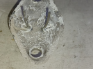
Could your problem cause by 2N3054 ? If not install properly, either pin will short to the chassis.

1709910039236.png
 
@Peter lye : I check the 2N3054, it doesn't touch the chassis. But I think it's not a genuine one, the width between the leg is not standard and the case start rusting at the same point even on the others I have in a box. So I decide to put the MJ15032G (the 12 I bought have almost a hfe around 60).


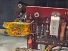
Quick update, I found the problem :), it came from the resistance R831 of the driver board F1170.
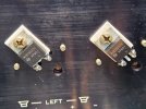
I forget the basic !! Check the voltage before everything.

As I replace the 2SD143 by a MJ15032G, I test the voltage of the collector of each transistor, I found that I had 4 volts between the left and right channel on the transistor that has the higher voltage. So I compare the voltage component by component and found that after the R831 the voltages drop wasn't the same.
So I decide to replace the resistance with the lowest drop of voltage. I measure the resistance and it was at 3,9K but wit the new "resistor" the drop of voltage was higher that the one that was on the other channel. I decide to change the other on with the same association to test.
The resistance have a value of 3,6k.

Now after the R831 resistor, I have around 32V which is the point 3.

The amp has still a light hum but it's ok.


So I will have to order theses resistor and replace the other resistors and other upgrade that Leestereo have done.
 

Attachments

  • 2SD143_Replacement.jpg
    2SD143_Replacement.jpg
    134.3 KB · Views: 53
  • R831_Falty.jpg
    R831_Falty.jpg
    125.3 KB · Views: 50
Part 5: POWER SUPPLY AND CHASSIS-MOUNTED CAPACITORS

index.php


index.php


index.php


index.php


The stock 4000µF/80V capacitor at C002 was upgraded to a 10,000µF/80V Nichicon KG type. Similarly, the capacity of the capacitors at C004 (1000µF/35V), C008 (470µF/50V), C819 (2,200µF/35V) and C820 (2,200µF/35V) were upgraded to 2200µF/50V, 1200µF/63V, 4700µF/50V and 4700µF/50V, respectively. The output-coupling capacitors at C825 and C826 (1000µF/63V) were upgraded to 6,800/63V Nichicon KG types. The stock diode bridge (D001), which had developed a hairline crack near one of the mounting holes, was replaced with a 10A/600PIV one.

index.php


index.php


index.php


index.php


Hello all, thanks so much for all the invaluable information provided on this thread thus far.

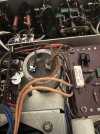
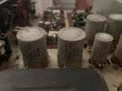
I am a novice repair man about to take on the challenge of restoring (in stages) my Sansui 777 amplifier. After recently opening her up for inspection I had noticed that the main power cap C002 seems to have blown (see image attached), so it only makes sense to start with the power stage capacitors as a first port of call. Up until now the amp has been functioning and sounding great.

I have followed some of the suggested replacement components on this thread and have a few initial questions. Firstly, why have most of the values and required voltages been substituted for much higher values in the list provided, was this intentional? Understandably some values seem harder to replace than others nowadays, however, where possible I have tried to makes the original spec and dimensions of the original caps. See list below.

Power Caps

C002 - 4000uF 80Vdc Elna - 40mm x 115mm / 4700uF 80Vdc Nichicon KG Type
C004 - 1000uF 35Vdc Elna - 22mm x 45mm / 1000uF 35Vdc Elna Cerafine POA
C006 - 500uF 50Vdc Elna - 22mm x 45mm / 470uF 50Vdc Elna Cerafine POA
C819/20 - 2000uF 35Vdc - 30mm x 45mm / 2200uF 63Vdc Audio Note
C825/26 - 1000uF 63Vdc - 35mm x 52mm / 1000uF 63Vdc Audio Note


Any other advice, comments or further suggestions on the above would be very much appreciated.


Dan
 

Attachments

  • IMG_5788.jpeg
    IMG_5788.jpeg
    106.6 KB · Views: 25
  • IMG_5789.jpeg
    IMG_5789.jpeg
    49.9 KB · Views: 25
  • IMG_5793.jpeg
    IMG_5793.jpeg
    61.6 KB · Views: 22
  • IMG_5790.jpeg
    IMG_5790.jpeg
    60.8 KB · Views: 22
Your question can be answered in the below thread , started by Leestereo:

 
Your question can be answered in the below thread , started by Leestereo:

This answers most of my questions for now, many thanks for sharing, will report back with findings.

Many thanks,

Dan
 
Last edited:
I wanted to promote some discussion here regarding substitutions for the 2sc458. If you want a deeper look into what part may work in a particular substitution it’s important to look past the first page of the datasheet and to look at the graphs (hopefully) provided.

This way you can exact values for the operating point of the transistor in question. That leads to the second point: a lot of important specs are for a given collector current so it’s good if you learn how to calculate the collector current for any given situation.

For example if you look at the fT for the ksc945 and ksc1845, they are actually quite close at 1 mA collector current even thought typical values listed on the first page are quite different.

My point is there is value into better understanding the datasheet to help make more informed decisions. Doing so will show you that the ksc1845 is in fact a superior substitution in some positions in this amp.

It’s also important to verify with measurements and your ears.
 
Last edited:
@Leestereo
I dont have the KSC945CG grade transistors to replace the small signal transistors 2sc458 LG and they are not available for sale in my region. I do have KSC945CY grade. I also have the original toshiba 2sc2240GR with hfe between 212 to 224 which seems like a good candidate for replacement of 2SC458. The issue is that I need 16 transistors for replacement but I have only 15 pieces of 2SC2240. Is there a possibility of using some other transistor (may be 2 pairs) as replacement and use 2sc2240 in rest of the places.. If yes, which transistor should I use and in which location(s).

I also have KSC1845 and KSC1815 in good numbers

Please share your valuable suggestion.
Regards
 
I'm not sure how I found this thread, from FB. I do have 777 100% stock has the blue protecting film abd working. But things should be change. So I'll read carefully, and like it
 

Attachments

  • inbound6325890596703054596.jpg
    inbound6325890596703054596.jpg
    54.9 KB · Views: 13
  • inbound362380671716492539.jpg
    inbound362380671716492539.jpg
    110.1 KB · Views: 11
Finally, the 777a has been restored. A huge shout out to all the learned people who solved my queries and helped me during the journey of this restoration especially @Leestereo whose restoration of 777a is a benchmark.

The amp was in very poor condition and it was disassembled for chassis derusting and nickleplating.

The top cover, bottom panel and the rear cover for the output transistors were powder coated.
 

Attachments

  • IMG-20260911-WA0021.jpg
    IMG-20260911-WA0021.jpg
    109.5 KB · Views: 26
  • IMG-20260911-WA0009.jpg
    IMG-20260911-WA0009.jpg
    96.9 KB · Views: 27
Back
Top Bottom