• The move to the new server is done. There are some software and database maintenance updates in process. This has us passing the hat around to help out. We appreciate any donations. Seriously, even a dollar helps. The payment page may be found here - https://www.audiokarma.org/support.html

Leestereo's Restoration & Upgrade of a Sansui AU-517

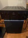
It's a pretty clean unit, BEFORE I cleaned it up. :)IMG_5725.JPGIMG_5728.jpg
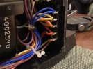
It was set for 100Volts. That seemed a little odd. I moved the jumper to 120Volt setting. Not even sure why I looked under that cover but maybe my spidey-sense was tingling.
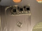
IMG_5729.jpg
Broken plastic parts, thanks FedEx.

IMG_5730.jpg
Broken plastic part. I'm assuming those are isolated binding posts, and I should ignore... Maybe just a cosmetic issue.
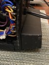
IMG_5731.jpg
Another angle. The bend is tiny, probably 1/8" or a few mm. The picture makes it look worse.
 
What value did you usw for the Nichicon ES and the smaller WIMA cap on Tone Control Circuit Board (F-2673)?
Same value as original?
 
Both 10uF and 22uF are fine here; the high-pass F3 for these values are 0.06Hz and 0.03Hz, respectively in the tone control feedback circuit.
Thanks, I'm glad I didn't make a mistake.
Almost got exited for an excuse to open her up and play around inside again.
 
Part 2: Driver Circuit Boards (F-2721 & F-2722)

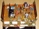
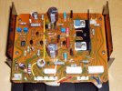
On the F-2721 (left channel) and the F-2722 (right channel) Driver boards, a total of 31 components were replaced. The local decoupling capacitors were upgraded to higher capacity low ESR types; the 22V zener diodes were replaced with 2% precision/low noise variants and their noise filters were replaced with higher capacity low ESR types; the Vbe multiplier by-pass capacitor was upgraded to a film type; the signal path polyester film capacitors were upgraded to polypropylene film types; and the trimmers for adjusting the bias current and the DC offset were upgraded to high-stability cermet types. The component damage from the in-famous OEM corrosive glue was minimal (only 1 additional resistor needed replacing); the glue residue was completely removed prior to the installation of replacement components. Note that F-2721 and F-2722 boards and the component complement used in the AU-517 are essentially identical (some resistor values are slightly different) to those in the AU-717.

index.php


index.php


index.php


index.php
Hi Ben,

I noticed that in this restoration, you replaced C12 with a film cap, whereas in your AU-717 restoration, you replaced it with a low ESR type. Would there be much of an improvement to do the film cap replacement? Also, the same for the green polyester cap replacement with polypropylene?

Thank you,
Gavin
 
Hi Ben,

I noticed that in this restoration, you replaced C12 with a film cap, whereas in your AU-717 restoration, you replaced it with a low ESR type. Would there be much of an improvement to do the film cap replacement? Also, the same for the green polyester cap replacement with polypropylene?

Thank you,
Gavin
IIRC, at the time of the AU-717 restoration, Mouser were out of stock of the WIMA MKS2 1uF capacitors; and that is why an electrolytic type was installed. My preference is for a film type in this location (Vbe multiplier by-pass capacitor), and IMO it does afford an improvement in the high frequency performance, at least theoretically. Also, I install the 1uF film in the C13 board location, as I do not think that upgrading the the stock polyester capacitor is necessary. However, I do recommend upgrading the stock 1.8nF polyester capacitors at C15 and C16 to polypropylene types.

F-2721 restored.jpg

F-2722 restored.jpg
 
IIRC, at the time of the AU-717 restoration, Mouser were out of stock of the WIMA MKS2 1uF capacitors; and that is why an electrolytic type was installed. My preference is for a film type in this location (Vbe multiplier by-pass capacitor), and IMO it does afford an improvement in the high frequency performance, at least theoretically. Also, I install the 1uF film in the C13 board location, as I do not think that upgrading the the stock polyester capacitor is necessary. However, I do recommend upgrading the stock 1.8nF polyester capacitors at C15 and C16 to polypropylene types.

View attachment 3796099

View attachment 3796101
Thanks Ben! I see on this one you place it in the bypass cap position. What is going on with R32? It appears you've replaced it with a capacitor.

Edit: Nevermind, I see you addressed this in another thread. That was an original capacitor across R32. Just a production change.
 
Last edited:
Back
Top Bottom