• The move to the new server is done. There are some software and database maintenance updates in process. This has us passing the hat around to help out. We appreciate any donations. Seriously, even a dollar helps. The payment page may be found here - https://www.audiokarma.org/support.html

Leestereo's Restoration/Upgrade of a Sansui AU-555A

Looks like nice work otherwise! Swap those transistors around and let us know how it goes! Curious why you never replaced the driver amp board transistors??

First of all, Thank you all for your help in this matter. It is good to know that I am not stuck alone with my own-made problem!

Being a complete Newbie.... I tried to follow Leestereo's instructions. Did I miss that part? Which TR numbers do the transistors have on the circuit board? (since I have no clue where to look for the driver amp board transistors)......
 
On the Main Amplifier board (F-1266-1), the only transistors that need to be replaced are the 2SA726s at TR801 and TR802 (which matjo has already replaced).
 
hello everybody, it is Holland again with a little update. Thanks to the input of all of you I found out the following:
1. I soldered the transistors the wrong way around. De- and Re-Soldered them and now there is music (at least from one channel).
2. I bypassed the Tone Circuit Board as suggested by Slimecity, to find out the Main Amp Circuit Board is working perfectly.

It is still not perfect, I need to go deeper back into the Tone Circuit Board (the Pots needs cleaning, only one channel is playing, the sound is far from perfect). I will follow up tomorrow.
 
Goodmorning everybody,

One step further..... Still figuring out why there is no sound to be heard from the left channel....
So far I figured out the following:
1. The TR701-TR704 Resistors on the Tone Control Board were placed wrong - Replaced them with new ones (KSC1845 with approx. ~385 hFE, all of them, could not find ones with ~450).
2. There is sound from the left channel, but almost not hearable (even on 100% volume). Checked it with headphones, the same (sound is stereo, so it is no "leakage" from the right channel).
3. If I bypass the Tone Control Board (using the Main Input on the back), the sound is equal loud on both channels. So Main Amp is working properly I suppose.

The Tone Control Board was the first Board I worked on (first board EVER, soldering for the first time in my life), so there might have gone something wrong there...

How can I find out why the volume is so extremely low on the left channel? Could the problem be on the Tone Control Board?
Did I use the right replacement-parts? Does the tolerance of the Capacitors have any influence? Does a large difference Working Voltage (110V in stead of 50V) matter? Is the Brand of the Capacitors important (Mouser did not always have exactly the same at stock as LeeStereo suggested)?

Your help is so much appreciated. Know already for sure that this is going to be my new lifetime hobby; learning every day!

PART 2. Tone Control Block F-1272-1
C701-C702 Film Capacitors .47uF 100V 10% Cornell Dubilier 598-474MSR100K
C707-C708 Aluminium Electrolytic Capacitors - Radial Leaded 25volts 10uF 85c 5x11 2LS Nichicon 647-UES1E100MDM
C723-C724 Aluminium Electrolytic Capacitors - Radial Leaded 25volts 10uF 85c 5x11 2LS Nichicon 647-UES1E100MDM
C725-C726 Film Capacitors 0.33 uF 100V 10% Cornell Dubilier 598-334MMR100K
C717-C718 Film Capacitors 1uF 50 Volts 10% WIMA 505-MKS02-1/50/10
C705-C706 Aluminium Electrolytic Capacitors - Radial Leaded 6.3volts 100uF 85c 5x9 2LS Nichicon 647-URS0J101MDD
C721-C722 Aluminium Electrolytic Capacitors - Radial Leaded 10V 47uF -55 to 105C Nichicon 647-UKA1A470MDD1TD
solder side (DC filtering) Aluminium Electrolytic Capacitors - Radial Leaded 35VDC 33uF 5x11mm LS 5.0mm Panasonic 667-EEU-FR1V330B
TR701-TR704 Bipolar Transistors - BJT NPN Epitaxial Sil ON Semiconductor 512-KSC1845FTA
C709-C710 Film Capacitors 50volts 0.033uF 10% LS 5mm KEMET 80-MMK5333K50J01L4
C715-C716 Film Capacitors 50volts 0.033uF 10% LS 5mm KEMET 80-MMK5333K50J01L4
C713-C714 Film Capacitors 0.008uF 100Volts Cornell Dubilier 598-185822J100RAB-F
C711-C712 Multilayer Ceramic Capacitors MLCC - Leaded KEMET 80-C323C202KAG5TA

 
And one more thing.....

I tried an other input (Tuner in stead of AUX), this also did not make the left channel coming alive.
Also plugging in a turntable did not bring the left channel to the right level. The good news: It looks like the Equalizer (Phono-preAmp) is working fine!
 
How can I find out why the volume is so extremely low on the left channel? Could the problem be on the Tone Control Board?

Yes, the fact that direct input to the power amplifier gives sound on both channels indicates that the problem is upstream in the preamp/tone stage. Have you cleaned all of the swiches with contact cleaner?

Did I use the right replacement-parts? Does the tolerance of the Capacitors have any influence?...Is the Brand of the Capacitors important (Mouser did not always have exactly the same at stock as LeeStereo suggested)?
The parts list you have posted is generally fine, as long as the replacement component is of the same type (e.g., low ESR, bipolar, film...etc..) as recommended, there is no problem using different brands. Since the left and right channels are identical, and you have sound in one channel, then it is not your component selection.

Does a large difference Working Voltage (110V in stead of 50V) matter?
Not sure what you are referring to here, the mains AC voltage in North America is 120V.
 
I tried to clean the switches as good as possible (without taking them out). Could not really find a proper "hole" to spray the fluid through......

Not sure what you are referring to here, the mains AC voltage in North America is 120V.
Sorry for the unclarity, what I was trying to say is if it would matter if the DC voltage of the device (sometimes 6.3V, many times 25 or 50 V) of the replacements were way much higher than the originals. Actually you answered this already by saying that the component-list was generally ok since the left channel is working properly.

I am running out of options, solely based on my logical thinking (since I have no electrical knowledge background). Is re-doing the entire left channel path on the tone-control-board a logical option to try out?
 
Perhaps, if you are certain the components are installed correctly, to maybe go over the soldering? Sometimes you will discover lifted pads that no longer make contact with the rest of the trace.. Possible that you discover something forgotten or misplaced while going over the previous work.
 
Post additional close-up pictures of the solder side of the tone board (F-1272-1). Clean board of flux residue and look for unintended solder bridges and/or cold solder joints.
 
If needed, I have no problems in re-doing the entire left channel soldering with new components on the Tone Circuit Board.
This issue makes me very curious, I am reading as many articles as possible, learning so much. Last time I studied so much was at the University (but that was economics, not electrical circuits). This is so much more fun!
 
Mr. Leestereo, from now on you are my Sansui Recap/Restoration/Upgrade Guru! I cannot find the words to show how much I appreciate the time, patience and effort you have spend on this Newbe being me. The Sansuie AU-555A is working 100% and the sound is spot on. I will send you a PM to discuss how I can get this great Dutch Gouda Cheese to you as my way of saying thank you. Up to the next challenges, fixing the AU-505, AU-2900 and AU-2000.

Also a big appreciation for the input by The Fuxtor and Slimecity!!!!
 
I know that Lee is helping you with this but noted some things here. I dont have my board in front of me - Im at work.

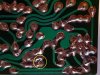
The area in the yellow circle shoud be resoldered/reflowed, its not great soldering there and there appears to be some component leads not properly soldered in.

Whats happening in the area with the red circle? There wasnt solder there before - it doesnt look like it is meant to be soldered - but there is a component leg sitting in there?

20190205_235548.jpg
 
...VR811-VR814 Trimmers on MAIN AMPLIFIER BLOCK: No idea how to set these up (don't have an Digital Oscilloscope), so left the screws untouched...

All that is needed to make appropriate adjustments of the AC balance and idle bias is a voltmeter/DMM. To adjust the AC balance, measure the voltage, wrt ground, at the +ve pin of the output capacitors C819 or C820 and adjust VR811 or VR812, respectively, to ~27V. To adjust the idle bias, measure the voltage across the emitter resistor, R843 or R844 and adjust VR813 or VR814, respectively, to 10mV.
 
Dear all, since I will start the new cruising-season soon (I work on a cruise ship), I will not be able to continue my new hobby in restoring Sansui-equipment. I will catch up by the end of this year, when I return again. Again, thank you to all for all the help you have been giving.
 
Hi i’m new to this forum and thinking of recap my au555a , ( sorry for my not wellwriten language )
My question is If You leestereo have a sort of list that i / we could use to se the originalparts and wath they shall be replaced with? As a shoppinglist so to speak, locks like You are the one to ask

Kind regards
Mathias from sweden
 
Back
Top Bottom