• The move to the new server is done. There are some software and database maintenance updates in process. This has us passing the hat around to help out. We appreciate any donations. Seriously, even a dollar helps. The payment page may be found here - https://www.audiokarma.org/support.html

Luxman L-100 woes

I don't know. All I have is a schematic. The purpose is to see if the circuit at C01, C02 is putting too much load to the transformer, or there is a weakness in the transformer itself.
 
I don't know. All I have is a schematic. The purpose is to see if the circuit at C01, C02 is putting too much load to the transformer, or there is a weakness in the transformer itself.
Ok I removed the plug and tested the VAC voltage from c01 and c02 plug connector and get the same reading of 10.1V
 
Updated photo of power supply board for reference
 

Attachments

  • IMG_0818.jpeg
    IMG_0818.jpeg
    136 KB · Views: 20
  • IMG_0816.jpeg
    IMG_0816.jpeg
    152.4 KB · Views: 20
Quick update, with the help of mbz there’s been some good progress made, removing the connector plug c11-18m from the right channel board the dim bulb dims which narrows the problem to this board, left channel appears fine. C01s-06s was removed at same time of the test.

This channel has all original transistors still with the exception of 2sc1079 and 2sa679 which were replaced with mj21193/4 as they were previously tested as leaking
 
In your first picture (post #24), I see that the collector legs have been cut and the transistors are mounted with an insulating washer on the bolt. What makes the electrical connection to the collector then?
 
In your first picture (post #24), I see that the collector legs have been cut and the transistors are mounted with an insulating washer on the bolt. What makes the electrical connection to the collector then?
Good eye for detail :) the screw goes through to a supporting leg underneath to the board I’ll try get a pic, I checked a continuity test there and pretty certain collector is connected to the board
 
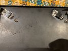
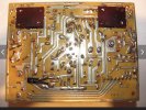
Here’s some photos of how the T0-66 used to be fitted and the connection system I could find online first photo is rear of the power supply second photo shows from an aeroplane view and the last shows the collector was also insulated originally when fitted with the TO-66
 

Attachments

  • IMG_0825.jpeg
    IMG_0825.jpeg
    227.2 KB · Views: 10
  • IMG_0826.png
    IMG_0826.png
    568.4 KB · Views: 10
  • IMG_0695.jpeg
    IMG_0695.jpeg
    108.4 KB · Views: 10
Usually, the TO-66 socket is insulated from the heat sink, and the electrical connection to the collector (case) is made by the screws. It is important that the screws don't touch the heat sink. But the mounting screw for the TO-220 transistors must be in electrical contact with the flange (collector) of the transistors. I'm not sure that your insulating washers are properly located. It could be possible that one of your mounting screw makes contact with the heat sink.
 
the last shows the collector was also insulated originally when fitted with the TO-66
The case of the TO-66 is insuated from the heat sink with a large mica insulator, but the mounting screws are not insulated from the transistor flange. There are metal lock washers under the screw heads, but no nylon washers.
 
Last edited:
The case of the TO-66 is insuated from the heat sink with a large mica insulator, but the mounting screws are not insulated from the transistor flange. There are metal lock washers under the screw heads, but no nylon washers.
Ok I will remove the nylon washers I have on the to-220 transistors and replace back with the metal washers and make sure the screw isn’t touching the heat sink
 
The case of the TO-66 is insuated from the heat sink with a large mica insulator, but the mounting screws are not insulated from the transistor flange. There are metal lock washers under the screw heads, but no nylon washers.
Ok some updates

I’ve removed the plastic screw insulator for the to-220 transistors

Initially I couldn’t get a consistent reading on sv03 with a diode check it was intermittent, removed and resoldered it in, powered up and hardly any dim which is great however with some tapping on the heat sink the brightness increases again but less than before, there is less dim if you remove that plug all together from that board
The voltages of the plug c11m-18 plug
C11 -56v
C12 +56v
C13 -47.2v
C14 -47.3v
C15 0v
C16 approx 140-200mv
C17m +46.6v
C18m +46.6v

Relay clicked out of protection doing these tests also which is positive

I have started to reflow the board again but it’s still intermittent with a tap on the heat sink I will replace the bias trimmer next to see if that makes a difference
 
Some further good news (I think) I have reflowed the board and replaced the bias trim pot, the dim now glows pretty low and the relay kicks out of protection even with the dim bulb connected I haven’t been able to replicate the fault again so far but will keep testing it before removing the dim bulb for a final bias and offset adjustment thanks everyone that has helped on this been a good learning experience
 
I spoke to soon with tapping on the heat sink the dim sometimes lights up again… bizarre the whole board is reflowed and looks clean I also reseated the outputs into their sockets I can’t see this being a broken track or solder joint I’m assuming a component leg might be nearly broken or something now
 
Long shot, try monitoring bias while tapping the heat sink, what happens to bias when DBT goes bright. Repeat for connector pins C11, C12, C13, C18. It does read like something is shorting on the heat sink.
 
Long shot, try monitoring bias while tapping the heat sink, what happens to bias when DBT goes bright. Repeat for connector pins C11, C12, C13, C18. It does read like something is shorting on the heat sink.
Thanks MBZ I’ll try get readings tomorrow I couldn’t get them today

I’ve think it’s related to the output transistor assembly sockets I cleaned them and refitted them I even put some plastic washers for the screw mounts to minimise any chance of them shorting somewhere, and it’s been much more consistent but still not perfect, adjusting the screw tension on the outputs can make a difference between a full bulb lit up or a low dim, I’ll report back once I take those measurements
 
Long shot, try monitoring bias while tapping the heat sink, what happens to bias when DBT goes bright. Repeat for connector pins C11, C12, C13, C18. It does read like something is shorting on the heat sink.
Ok here are the voltages with a very bright dim bulb

C11 -4.3v
C12 +1.6v
C13 -2.1v
C17 and c18 +2.2v
 
Quick update sv03 looks like it’s shorted or very intermittent I swapped boards from one channel to another and the problem followed the other channel which I was able to verify when removing the c11-18 plug, sv03 definitely is suspect I’ve ordered some 1n4150 to replace it
 
Good news finally! The 1n4150 arrived today I made up 3 of them in series and wrapped them in heat shrink and mounted to the board, pleased to say the dim bulb dims low now and is not intermittent after many attempts and taps with my rubber mallet on the heat sink - comes out of protection fine and the voltages all seem stable now.

Sv03 was definitely the culprit showing a different reading every hour or so when I checked in or out of circuit.

Thanks @ecluser and @mbz for your help I’ll redo the bias and offset tomorrow before a final reassembly glad to have found the culprit
 
  • Like
Reactions: mbz
So the Luxman woes continue after further checks a new fault has emerged with the relay clicking in and out of protection, I have narrowed this down to the left side preamp, if I disconnect the left hand power amp module the amp works fine and I have swapped both modules to verify the fault lies within the left hand pre amp side.

Q421base voltage +1.31v start up relay clicks spikes to -24v

Q431 base voltage -1.2v on start up relay clicks spikes to +14v

Pb640 flat amp has had all its transistors and capacitors replaced with the fault still occurring I used ksa992 and bc550cta - the fault was apparent prior and after to this refurb.

Where should I look next to pin point this? Pb636 eq board??
 
Back
Top Bottom
